AS Series Operation Manual
12-26
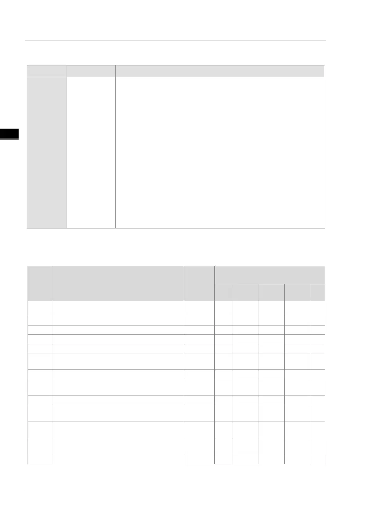
Descriptions
Module Type LED indicator Descriptions
CPU
Error LED
There are five types of error indicator states for of the CPU module errors,
including LED indicator ON, OFF, blinking fast, blinking normally, and blinking
slowly. When the LED indicator is ON, blinking fast/normally, clear the problems
first in order to run the CPU module. When the LED indicator is blinking slowly,
indicating a warning type of error codes, it does not require immediate action.
Clear the problems when the module is powered off.
Error type:
ON: A serious error occurs in the module.
Blinking fast (every 0.2 seconds): unstable power supply or hardware
Failure.
Blinking normally (every 0.5 second): system program errors or system
cannot run.
Warning type:
Blinking slowly (every one second and off for three seconds): a warning is
triggered, but the system can still run.
OFF: a warning is triggered, but the system can still run. You can modify the rules
of how a warning is triggered, or use the SM/SR to show the warnings.
12.4.1
Error Codes and LED Indicators for CPU Modules
Note: refer to Section 12.3 for the status descriptions of the Error LED indicators.
Error
code
Description
CPU
status
ERROR LED indicator status
ON
000A
Scan timeout
Stop V
The program in the PLC is damaged.
The access to the memory in the CPU is denied.
The PLC password is incorrect.
0026
RTC cannot keep track of the current time (the
battery LED is blinking.)
Continue
0027 Battery low (the battery LED is ON.) Continue
002A
24VDC power supply is not sufficient and then is
recovered from low-voltage for less than 10 ms.
Continue V
The PLC maximum password attempts exceeded.
002E
The access to the external memory of the CPU is
Stop V
002F
PLC programs are not consistent with the system
Stop V
0050
The memories in the latched special auxiliary relays
are abnormal.
Continue V
The latched special data registers are abnormal.
 Loading...