Chapter 8 Communications ASDA-B2
8-10 Revision May, 2018
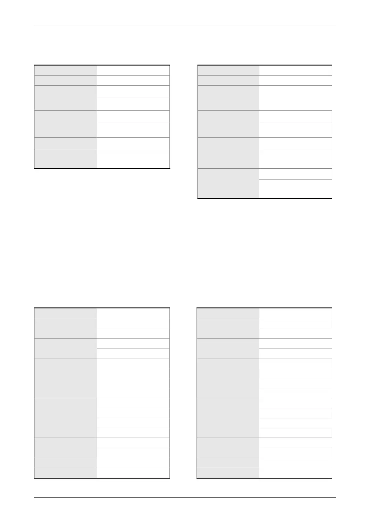
RTU Mode:
Command message (Master): Response message (Slave):
Slave address 01H Slave address 01H
Function 03H Function 03H
Starting data
address
02H (High)
Number of data
(In Byte)
04H
00H (Low)
Number of data
(In Word)
00H
Contents of
starting data
address 0200H
00H (High)
02H
B1H (Low)
CRC Check Low C5H (Low)
Contents of
second data
address 0201H
1FH (High)
CRC Check
High
B3H (High)
40H (Low)
CRC Check Low A3H (Lower bytes)
CRC Check
High
D4H (Upper bytes)
Note: Before and after the transmission in RTU mode, 10 ms of silent interval is needed.
Example 2: function code 06H, write single word:
The Master issues command to the 1
st
Slave and writes data 0064H to address 0200H.
The Slave sends the response message to the Master after the writing is completed.
The calculation of LRC and CRC will be described in next chapter.
ASCII Mode:
Command message (Master): Response message (Slave):
Start ‘:’ Start ‘:’
Slave address
‘0’
Slave address
‘0’
‘1’ ‘1’
Function
‘0’
Function
‘0’
‘6’ ‘6’
Starting data
address
‘0’
Starting data
address
‘0’
‘2’ ‘2'
‘0’ ‘0’
‘0’ ‘0’
Content of data
‘0’
Content of data
‘0’
‘0’ ‘0’
‘6’ ‘6’
‘4’ ‘4’
LRC Check
‘9’
LRC Check
‘9’
‘3’ ‘3’
End 1 (0DH)(CR) End 1 (0DH)(CR)
End 0 (0AH)(LF) End 0 (0AH)(LF)
 Loading...


