Disconnect in the “OFF” position, verify the PV input polarity
once more simply by carefully using a 600 V, DC rated digital
volt meter and probing the positive (+) and negative (-) PV array
connections.
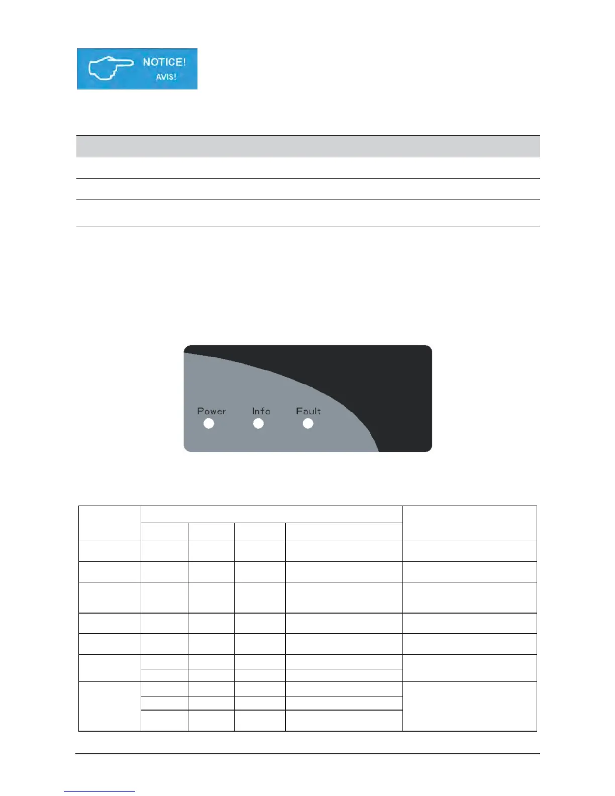
5.1 Status LEDs
Label Designation Color
Power Operation Green
Fault Fault Red
Info Infomation Yellow
Information on the LED messages is provided in “8. Diagnosis and maintenance”.
5.2 LED Indication
5.2.1 Introduction
Function
There are 3 LEDs in the front side of the inverter
5.2.2 LED Message
The LEDs indicate the operational status of the inverter
Message
Category
LED Signal
Message Explanation
LED Color Status Behavior
POWER Green <On> Constant on The inverter feeds in grid.
Sync. POWER Green <Blink> 1s on, 1s off
The inverter is synchronizing
with grid.
Information INFO Yellow <On> Constant on
The inverter has alarm and
user can search for details via
FAULT Red <On> Constant on Grounding fault occurs.
FAULT Red <On> Constant on
The inverter has fault and user
can search for details via APP.
The inverter is under firmware
upgrade.
Initialization
POWER Green <On> On until done
Inverter initialize when the DC
voltage rise to startup
threshold.
INFO
Yellow <On> On until done
FAULT Red <On> On until done
 Loading...