1 Analog Input Module DVP04AD-E2
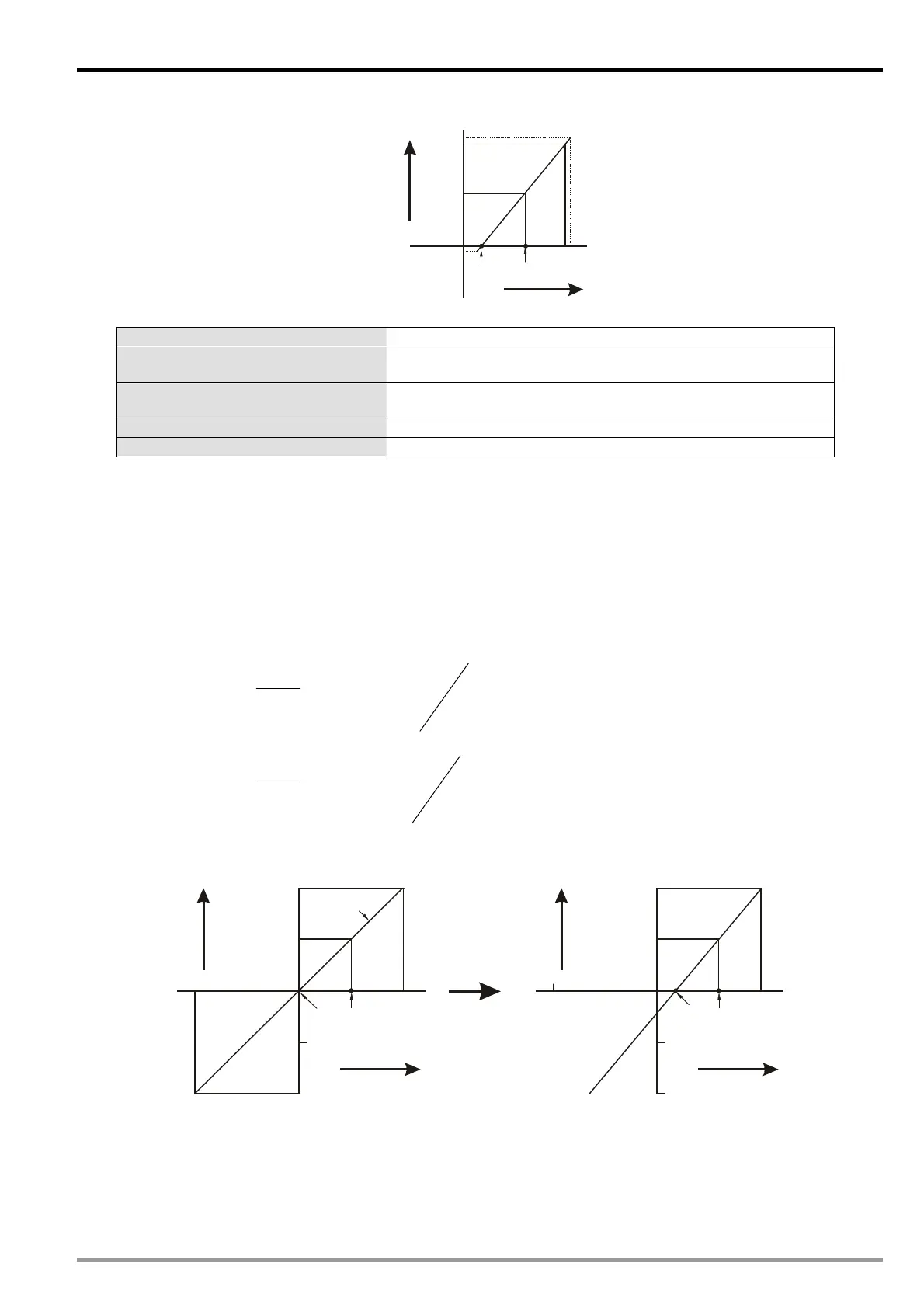
Mode 6 (H’00
06): (+4mA ~ +20mA)
+32000
4mA
0
Offset
20mA
12mA
Gain
+16000
Digital
output
Current input
+32384
-384
Mode 6 of CR#2~ CR#5 +4mA ~ +20mA, Gain = 12mA (19,200), Offset = 4mA (6,400).
Gain (CR#28 ~ CR#31)
The corresponding current input value when the digital output
value = 16,000.
Offset (CR#34 ~ CR#37)
The corresponding current input value when the digital output
value = 0.
Range of digital conversion 0 ~ 32,000
Max./Min. output range of digital data -384 ~ +32,384
1.7.3 Adjusting A/D Conversion Curve in Voltage Input Mode 0 & Mode2
1.
Description
Take 04AD CH1 for example, when CR#2 is set as voltage input mode (mode 0), the Offset value will be
set as 0V (0) and Gain value as 5V (5V/0.3215mV=16,000), i.e. input voltage -10V ~ +10V will correspond
to values -32,000 ~ +32,000.
When CR#2 is set as voltage input mode (mode 2), the Offset value will be set as 0V (0) and Gain value as
5V (5V/0.3215mV=16,000), i.e. input voltage 0V ~ +10V will correspond to values 0 ~ +32,000.
If you cannot use the default voltage input mode (mode 0 and mode 2), you can make adjustments on the
A/D conversion curve according to your actual needs. For example, set the Offset of CH1 as 2V
(2V/0.3215mV=6,400) and Gain as 6V (6V/0.3215mV=19,200).
OffsetGain
Offset
V
VX
Y
32000
)(10
)(
16000
Example: If X=6V, Y=?
16000
640019200
640032000
)(10
)( 6
16000
V
V
Y
You only need to set up the A/D conversion curve for once. Set up CR#40 (Set value changing prohibited)
to prevent incorrect operations.
2. Adjusted Curve
+32000
+16000
-16000
10V
-32000
-10V
5V
0
Mode 0
Gain
Offset
Digital
output
Voltage input
+32000
+16000
-16000
10V
-32000
-10V
6V
0
Gain
Offset
Digital
output
Voltage input
2V
3. Devices
X0 = On: Set the input mode of the signals in CH1 as mode 0.
X1 = On: Set Offset value of CH1 as 2V (6,400) and Gain value as 6V (19,200).
M0 = On: Disable CH1 set value changing.
DVP-ES2 Module Manual
1-13

 Loading...


