3 Mixed Analog Input/Output Module DVP06XA-E2
2. Current input mode
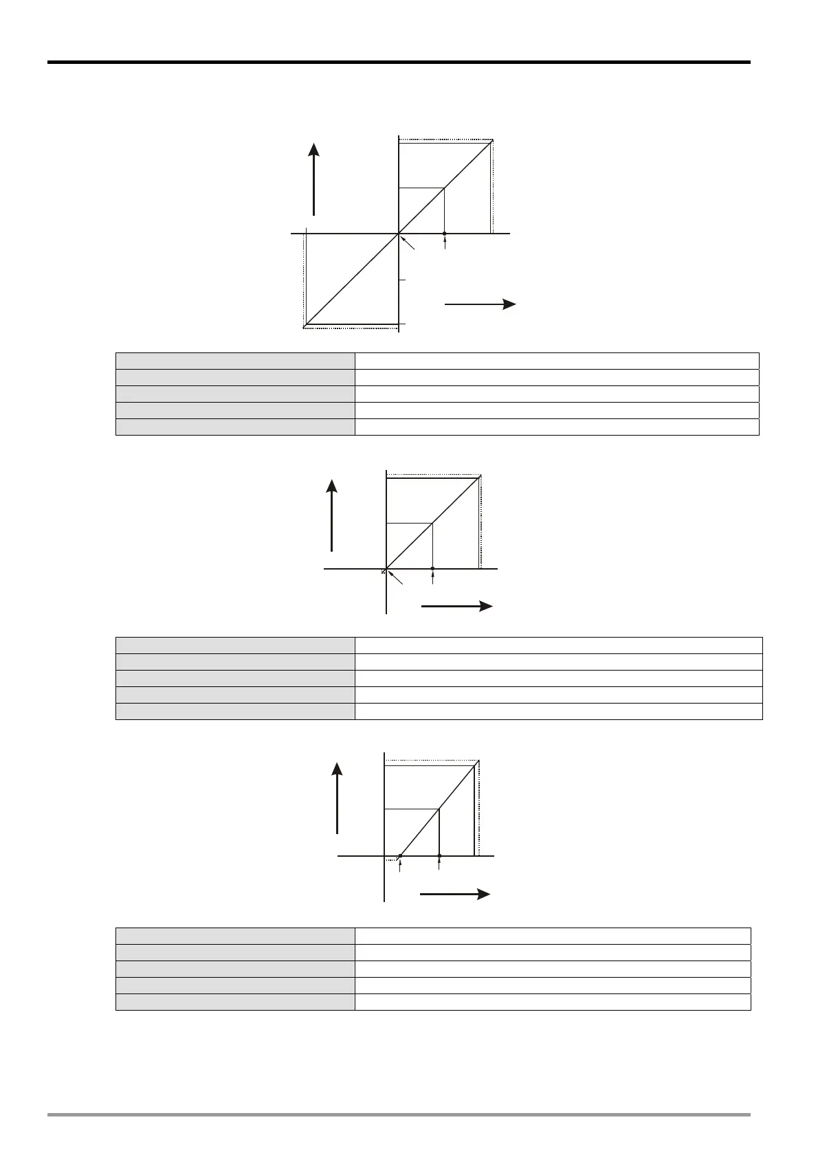
Mode 4 (H’0004): (-20mA~ +20mA)
+32000
+16000
-16000
20mA
-32000
-20mA
10mA
0
Gain
Offset
Digital
output
Current input
+32384
-32384
Mode 4 of CR#2~ CR#5 -20mA ~ +20mA, Gain = 10mA (16,000), Offset = 0mA (0).
Gain (CR#34 ~ CR#37) The current input value corresponds to digital value 16,000.
Offset (CR#28 ~ CR#31) The current input value corresponds to digital value 0.
Range of digital conversion -32,000 ~ +32,000
Max./Min. output range of digital data -32,384 ~ +32,384
Mode 5 (H’0005): (0 ~ +20mA)
+32000
+16000
20mA
10mA
0
GainOffset
Digital
output
Curren t input
+32384
-384
Mode 5 of CR#2~ CR#5 0mA ~ +20mA, Gain = 10mA (16,000), Offset = 0mA (0).
Gain (CR#34 ~ CR#37) The current input value corresponds to digital value 16,000.
Offset (CR#28 ~ CR#31) The current input value corresponds to digital value 0.
Range of digital conversion 0 ~ 32,000
Max./Min. output range of digital data -384 ~ +32,384
Mode 6 (H’0006): (+4mA ~ +20mA)
+32000
4mA
0
Offset
20mA
12mA
Gain
+16000
Digital
output
Current input
+32384
-384
Mode 6 of CR#2~ CR#5 +4mA ~ +20mA, Gain = 12mA (19,200), Offset = 4mA (6,400).
Gain (CR#34 ~ CR#37) The current input value when the digital output value = 16,000.
Offset (CR#28 ~ CR#31) The current input value when the digital output value = 0.
Range of digital conversion 0 ~ 32,000
Max./Min. output range of digital data -384 ~ +32,384
3.7.2 Adjusting D/A Conversion Curve of CH5 ~ CH6
You can adjust the conversion curves according to the actual needs by changing the Offset value (CR#32 ~ CR#33)
and Gain value (CR#38 ~ CR#39).
Gain (in DVP06XA-E2): The voltage (current) output value corresponds to digital value 16,000.
DVP-ES2 Module Manual
3-14

 Loading...


