3 Mixed Analog Input/Output Module DVP06XA-E2
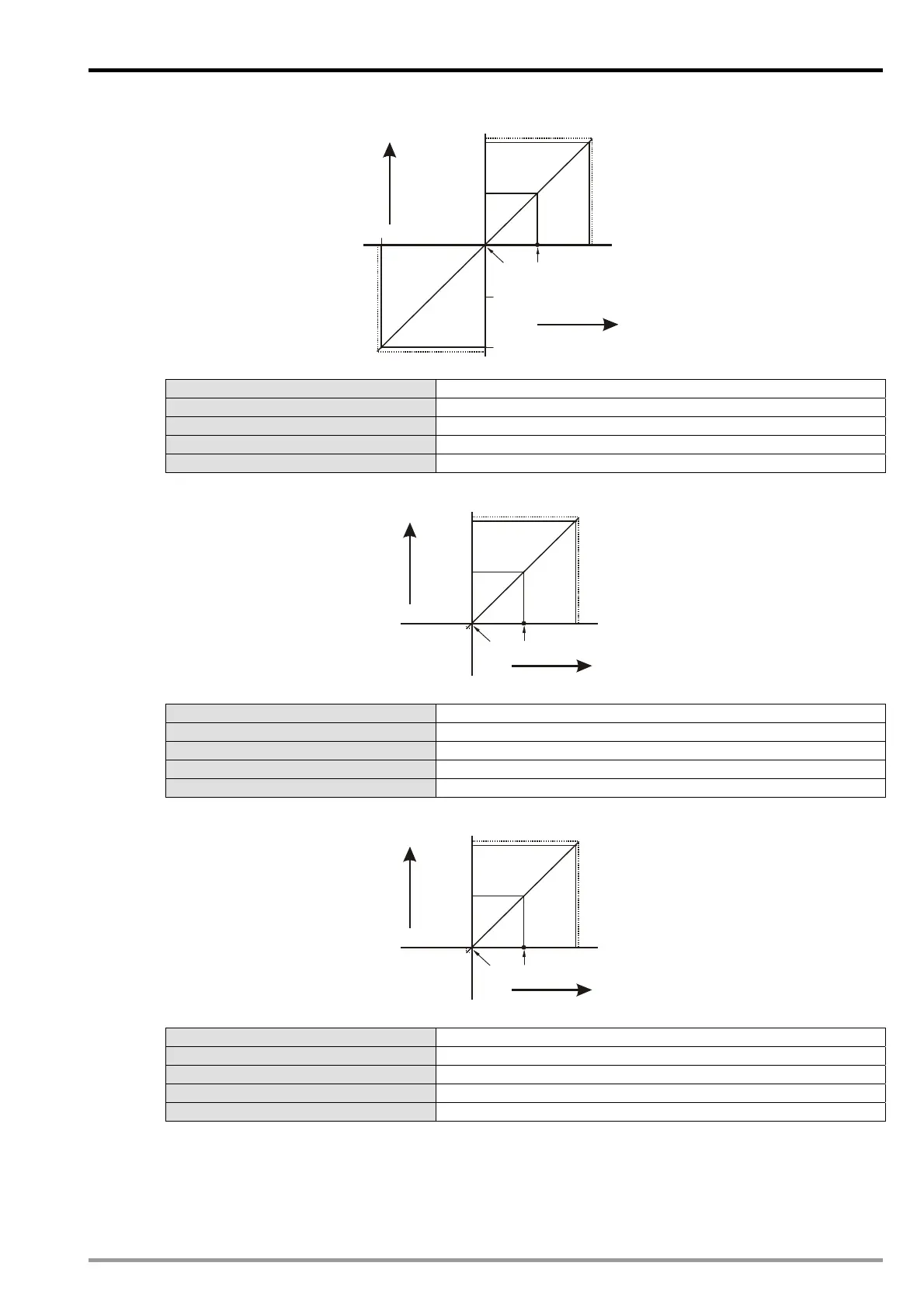
Mode 1 (H’00
01): (-5V ~ +5V)
Voltage input
+32000
+16000
-16000
5V
-32000
-5V
2.5V
0
Gain
Offset
Digital
output
+32384
-32384
Mode 1 of CR#2~ CR#5 -5V ~ +5V, Gain = 2.5V (16,000), Offset = 0V (0).
Gain (CR#34 ~ CR#37) The voltage input value corresponds to digital value 16,000.
Offset (CR#28 ~ CR#31) The voltage input value corresponds to digital value 0.
Range of digital conversion -32,000 ~ +32,000
Max./Min. output range of digital data -32,384 ~ +32,384
Mode 2 (H’0002): (0V~+10V)
Voltage input
+32000
+16000
10V
5V
0
Gain
Offset
Digital
output
+32384
-384
Mode 2 of CR#2~ CR#5 0V ~ +10V, Gain = 5V (16,000), Offset = 0V (0).
Gain (CR#34 ~ CR#37) The voltage input value corresponds to digital value 16,000.
Offset (CR#28 ~ CR#31) The voltage input value corresponds to digital value 0.
Range of digital conversion 0 ~ 32,000
Max./Min. output range of digital data -384 ~ +32,384
Mode 3 (H’0003): (0V~+5V)
Voltage input
+32000
+16000
5V
2.5V
0
Gain
Offset
Digital
output
+32384
-384
Mode 3 of CR#2~ CR#5 0V ~ +5V, Gain = 2.5V (16,000), Offset = 0V (0).
Gain (CR#34 ~ CR#37) The voltage input value corresponds to digital value 16,000.
Offset (CR#28 ~ CR#31) The voltage input value corresponds to digital value 0.
Range of digital conversion 0 ~ 32,000
Max./Min. output range of digital data -384 ~ +32,384
DVP-ES2 Module Manual
3-13

 Loading...


