2 Analog Output Module DVP02DA-E2/DVP04DA-E2
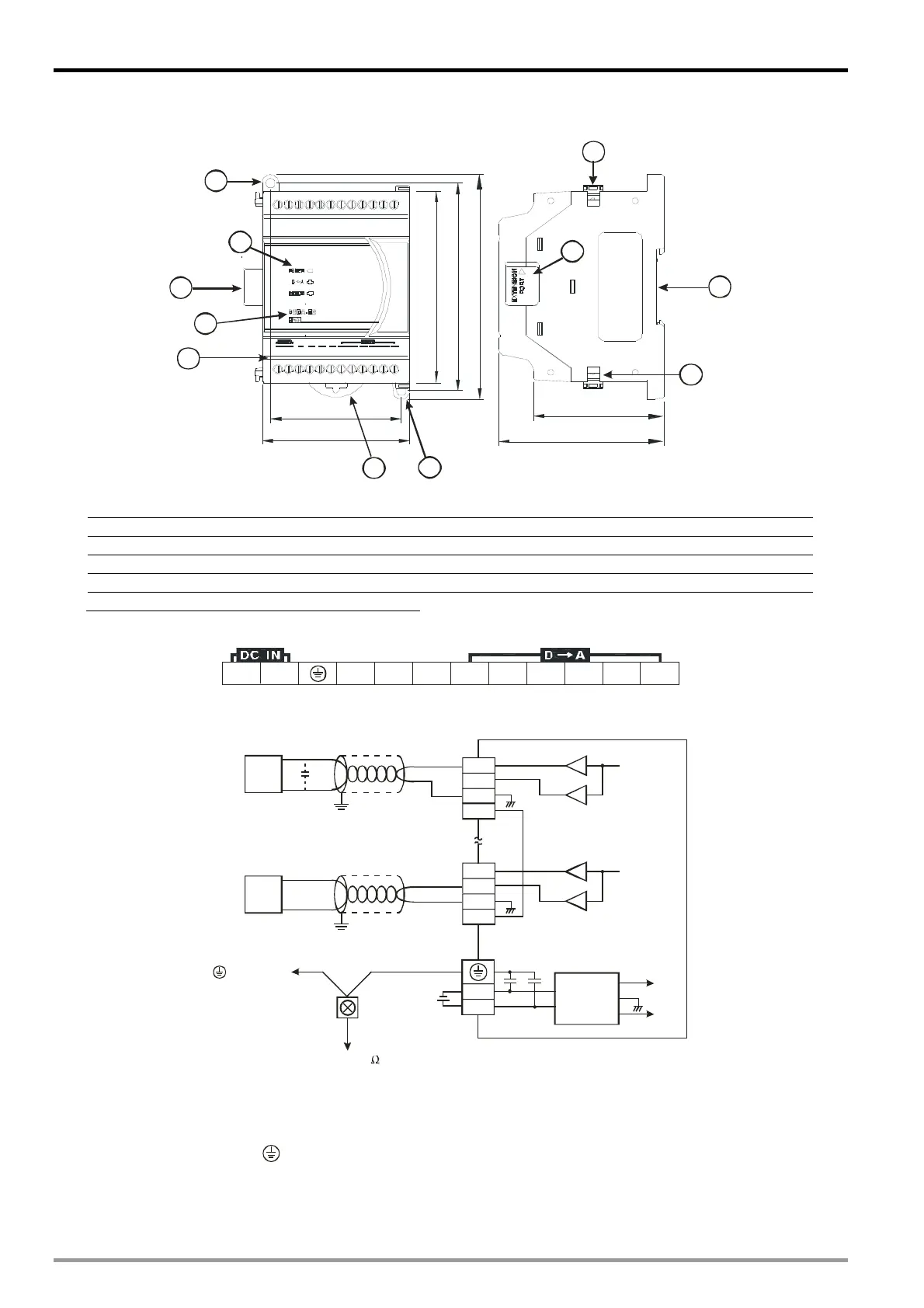
2.3.2 DVP02DA-E2
70
62
106
98
78
90
61.5
2
1
4
5
9
6
7
7
8
8
3
Unit: mm
1. Connection port for extension unit/module 6. Terminals
2. DIN rail (35mm) 7. Mounting hole
3. Model name 8. Fixing clip for extension unit/module
4. POWER, ERROR, DA indicators 9. Mounting port for extension unit/module
5. DIN rail clip
I/O terminals
24 V 0V FEFE VO2IO1FE VO1 AG AGIO2
2.4 External Wiring
VO1
IO1
AG
VO4
IO4
AG
0V
24V
DC/DC
converter
+15V
-15V
AG
FE
FE
CH1
CH1
-10V~+10V
*2
*3
0mA~20mA
DC24V
CH4
CH4
Volt ag e outpu t
AC motor drive,
recorder,
scale valve...
shielded cable *1
shielded cable *1
AC drive, recorder,
scale valve...
Current input
Ter mi n a l of
power module
system grounding
Grounding(100 or less)
*1: When performing analog output, please isolate other power wirings.
*2: If the ripples at the loaded input terminal are too significant that causes noise interference on the wiring,
connect the wiring to 0.1 ~ 0.47F 25V capacitor.
*3: Please connect the
terminal on both the power modules and DA to the system earth point and
ground the system contact or connect it to the cover of power distribution cabinet.
DVP-ES2 Module Manual
2-2

 Loading...


