3 Mixed Analog Input/Output Module DVP06XA-E2
3.1 The A/D and D/A Conversion
In industrial automation, many measuring units are transmitted by analog signals. The most frequently adopted range
for t he signals are voltage -10 ~ +10V and current -20 ~ +20mA. To use the analog signals as the parameters for PLC
operations, you have to convert them into digital values first. Furthermore, many control signals are analog signals.
The most frequently adopted range for the signals are voltage -10V ~ +10V and current 0 ~ 20mA. Therefore, the data
in the PLC have to be converted into analog signals for controlling the peripheral devices.
For example, the voltage -10 ~ 10V is first converted into values -32,000 ~ +32,000 by an XA module, and the PLC
will read/write the control registers (CR) in the XA module. The signals sent back to the PLC for operations will be
digital K-32,000 ~ K32,000. In addition, data -32,000 ~ +32,000 in the PLC are converted into voltage -10V ~ +10V by
an XA module. The output voltage can therefore be used for controlling the peripheral analog devices.
3.2 Introduction
The data in DVP06XA-E2 mixed analog input/output module receives external 4 points of analog input signals
(voltage or current) and converts them into 16-bit digital signals. For the analog signal output, DVP06XA-E2 receives
2 groups of 16-bit digital data coming from the PLC MPU and converts the digital data into 2 points of analog output
signals (voltage or current). The MPU can read/write the data in the module by using FROM/TO instructions or
D9900~D9999 in the program.
For the analog signal input, you can select voltage input or current input by the wiring. Range for voltage input: ±10V
(±32,000). Range for current input: ±20mA (±32,000).
For the analog signal output, you can select voltage output or current output by the wiring. Range for voltage output:
±10V (±32,000). Range for current output: 0mA ~ 20mA (0 ~ +32,000).
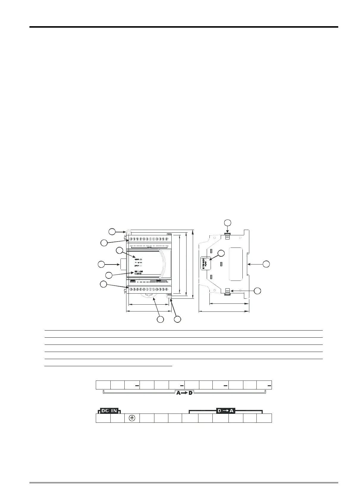
3.3 Product Profile and Outline
3.3.1 DVP06XA-ES2
70
62
106
98
78
90
61.5
2
1
4
5
9
6
6
7
7
8
8
3
+ + ++ + + + +
Unit: mm
1. Connection port for extension unit/module 6. Terminals
2. DIN rail (35mm) 7. Mounting hole
3. Model name 8. Fixing clip for extension unit/module
4. POWER, ERROR, AD indicators 9. Mounting port for extension unit/module
5. DIN rail clip
I/O terminals
VI1
+
I1V1
+
I3
+
I2
+
V2 V3
+
VI2 V4
+
VI3 VI4
+
I4
+
FEFE FE VO1 VO2AGIO1 IO2 AG24 V 0V
DVP-ES2 Module Manual
3-1

 Loading...


