1 Analog Input Module DVP04AD-E2
1.8.2 Measuring the Speed of AC Motor Drive
1.
Description
Assume we set the output frequency of VFD-B as 0 ~ 50.0Hz, which corresponds to the analog 0 ~ 10V
DC output supplied by VFD-B, and send it to DVP04AD-E2 to be converted into values. The voltage value
will be displayed in register D0.
After an operation, the voltage value in D0 will become the actual voltage value of VFD-B and the
converted frequency will be stored in register D4.
Set the input signals of A/D module as mode 2, i.e. the voltage input mode (0V ~ +10V).
2. Devices
D40: average digital value of input signals
D50: present digital value of input signal
D0: actual value of the present measured voltage
D4: actual frequency of VFD-B.
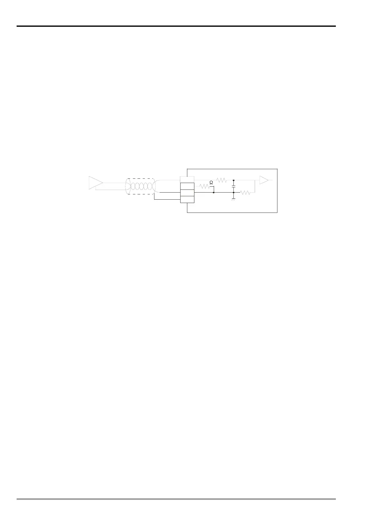
3. Wiring
Connect the analog voltage output 0 ~ 10V DC offered by VFD-B to CH1 of DVP04AD-E2 (as shown
below).
CH1
100K
250
0V~10V DC
V+
I+
COM
CH1
100K
AG
FG
AFM
ACM
VFD-B analog output
Shielded cable
4. Program explanation
When PLC goes from STOP to RUN, the analog output voltage VFD-B offers is 0 ~ 10V DC. Therefore, set
the input mode of DVP04AD-E2 as mode 2, i.e. voltage input mode (0V ~ +10V).
Save the present value of the input signal measured into D50.
In the voltage mode of DVP04AD-E2, The value range for 0 ~ 10V DC is K0 ~ K32,000. Data in D50 is
3200 times of the actual voltage value (i.e. 32,000/10V = 3,200). Divide the value in D50 by 3,200 and
store the value obtained into D0 which represents actual voltage measured.
Frequency range 0 ~ 50.0Hz corresponds to voltage output 0 ~ 10V. Therefore, multiply the value in D0 by
5 (50/10=5) and store the value obtained in register D4 for obtaining the actual output frequency of VFD-B.
DVP-ES2 Module Manual
1-18

 Loading...


