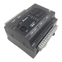
1 Analog Input Module DVP04AD-E2
5. Program example
Ladder diagram: Explanation:
Set as mode 2 (voltage input mode 0~10V)
Set the average times as 10.
Storing the measured average value of input
signal into D40.
Store the measured digital value of input
signal into D50.
D50/3200 = D0 (the actual voltage measured)
M1002
M1000
END
K0
K1TO
D9990 D40
K0 K1TO
D50 K3200
D0 K5
K2 K2
K10
MOV
DIV
MUL
K8
K0 K20 K1FROM
D0
D4
D50
D0*5 = D4 (the output frequency)
DVP-ES2 Module Manual
1-19

 Loading...