1 Analog Input Module DVP04AD-E2
1.5 Specifications
DVP04AD-E2 Voltage input Current input
Power supply voltage 24 VDC (20.4VDC ~ 28.8VDC) (-15% ~ +20%)
Connector European standard fixed terminal block (Pin pitch: 5mm)
Analog input channel 4 channels
Range of analog input ±10V ±5V ±20mA 0~20mA 4~20mA
Range of digital conversion ±32,000 ±32,000 ±32,000 0~32,000 0~32,000
Max./Min. output range of digital
data
±32,384 ±32,384 ±32,384 -384~+32,384 -384~+32,384
Resolution
14 bits
20V/64000
14 bits
10V/64000
14 bits
40mA/64000
13 bits
20mA/32000
13 bits
16mA/32000
Input impedance > 200 K 250
Overall accuracy
0.5% when in full scale (25°C, 77°F)
1% when in full scale within the range of 0 ~ 55°C (32 ~ 131°F)
Response time 3 ms / all channels
Isolation
Optical coupler isolation between digital circuits and analog circuits. No isolation among
analog channels.
500VDC between digital circuits and Ground
500VDC between analog circuits and Ground
500VDC between analog circuits and digital circuits
500VDC between 24VDC and Ground
Range of absolute input ±15V ±32mA
Digital data format 16 significant bits out of 16 bits are available; in 2’s complement
Average function Supported. Available for setting up average times in CR#8 ~ CR#11. Range: K1 ~ K100.
Self-diagnosis Upper and lower bound detection in all channels
Series connection to DVP-PLC
MPU
The modules are numbered from 0 to 7 automatically by their distance from MPU. Max. 8
modules are allowed to connect to MPU and will not occupy any digital I/O points.
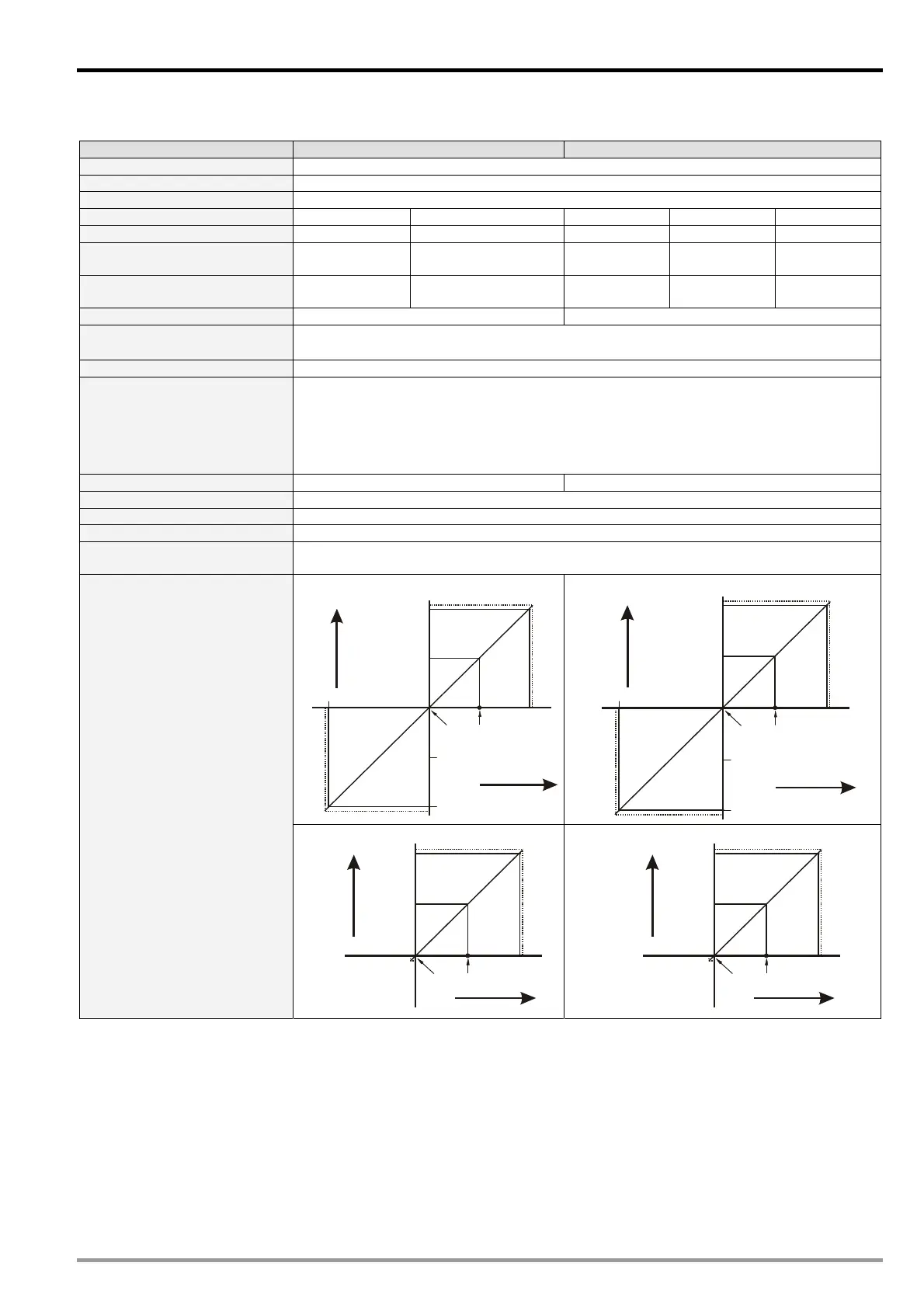
Mode 0 (H’0000): (-10V ~ +10V)
Voltage input
+32000
+16000
-16000
10V
-32000
-10V
5V
0
Gain
Offset
Digital
output
+32384
-32384
Mode 1 (H’0001): (-5V ~ +5V)
Voltage input
+32000
+16000
-16000
5V
-32000
-5V
2.5V
0
Gain
Offset
Digital
output
+32384
-32384
A/D conversion curve
(Default: mode 0)
Mode 2 (H’0002): (0V~+10V)
Voltage input
+32000
+16000
10V
5V
0
Gain
Offset
Digital
output
+32384
-384
Mode 3 (H’0003): (0V~+5V)
Voltage input
+32000
+16000
5V
2.5V
0
Gain
Offset
Digital
output
+32384
-384
DVP-ES2 Module Manual
1-3

 Loading...


