1 Analog Input Module DVP04AD-E2
If you cannot use the default current input mode (mode 4 ~ mode 6), you can make adjustments on the
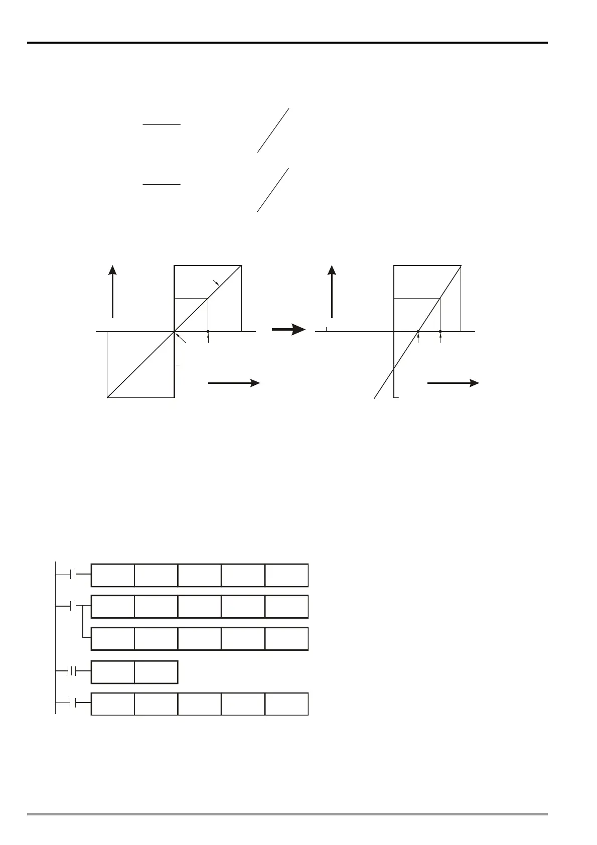
A/D conversion curve according to your actual need. For example, set the Offset of CH3 as 8mA
(8mA/0.625A=12,800) and Gain as 14mA (14mA/0.625A=22,400).
OffsetGain
Offset
mA
mAX
Y
32000
)(20
)(
16000
Example: If X=14mA, Y=?
16000
1280022400
1280032000
)(20
)(14
16000
mA
mA
Y
You only need to set up the A/D conversion curve for once. Set up CR#40 (Set value changing prohibited)
to prevent incorrect operations.
2. Adjusted Curve
+32000
+16000
-16000
20mA
-32000
-20mA
10mA
0
Mode 4
Gain
Offset
Digital
output
Current input
+32000
+16000
-16000
20mA
-32000
-20mA
14mA
0
GainOffset
Digital
output
Current input
8mA
3. Devices
X0 = On: Set the input mode of the signals in CH3 as mode 4.
X1 = On: Set Offset value of CH3 as 8mA (12,800) and Gain value as 14mA (22,400).
M0 = On: Disable CH3 set value changing.
4.
Program explanation
When X0 = On, set CR#4 as K4 (H’4) and the signal input mode in CH3 as mode 4 (current input mode).
When X1 = On, write K12,800 (Offset value of CH3) into CR#30 and K22,400 (Gain value of CH3) into
CR#36.
When X1 goes from On to Off, set M0 = On to disable the adjustment on A/D conversion curve. Write K4
(H’4) into CR#40 to disable CH3 set value changing.
5. Program example
Ladder Diagram: Explanation:
Set CH3 as mode 4 (current input mode)
Set the Offset value of CH3
Set the Gain value of CH3
X0
M0
X1
K0
K36 K1
K0 K40
K1
K0
K1
TOP
K0
K1
M0
TOP
TOP
TOP
X1
SET
H4
K12800
K22400
H4
K4
K30
Disable CH3 set value changing
DVP-ES2 Module Manual
1-16

 Loading...


