3 Mixed Analog Input/Output Module DVP06XA-E2
DVP-ES2 Module Manual
3-4
DVP06XA-E2
Analog/Digital (A/D) Voltage input Current input
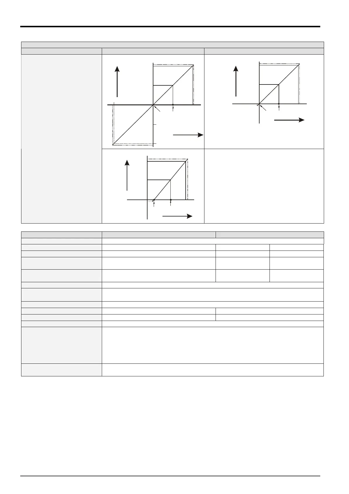
Mode 4 (H’0004): (-20mA~ +20mA)
+32000
+16000
-16000
20mA
-32000
-20mA
10mA
0
Gain
Offset
Digital
output
Current input
+32384
-32384
Mode 5 (H’0005): (0 ~ +20mA)
+32000
+16000
20mA
10mA
0
GainOffset
Digital
output
Current input
+32384
-384
A/D conversion curve
(Default: mode 0)
Mode 6 (H’0006): (+4mA ~ +20mA)
+32000
4mA
0
Offset
20mA
12mA
Gain
+16000
Digital
output
Current input
+32384
-384
Mode -1 (H’FFFF): Channel unavailable. Average
value and present value of input channels will be
displayed as 32767(H’7FFF)
Digital/Analog (D/A) Voltage output Current output
Analog output channel 2 channels
Range of analog output -10V ~ 10V 0 ~ 20mA 4mA ~ 20mA
Range of digital conversion -32,000 ~ +32,000 0 ~ +32,000 0 ~ +32,000
Max./Min. input range of digital
data
-32,768 ~ +32,767 0 ~ +32,767 -6,400 ~ +32,767
Resolution
14 bits
20V/64000
14 bits
20mA/32000
14 bits
16mA/32000
Output impedance 0.5 or lower
Overall accuracy
0.5% when in full scale (25°C, 77°F);
1% when in full scale within the range of (0 ~ 55°C, 32 ~ 131°F)
Response time 3 ms/ all channels
Max. output current 20mA (1K ~ 2M) -
Tolerance l o a d im pe dance - 0 ~ 500
Digital data format 16 significant bits out of 16 bits are available; in 2’s complement
Isolation
Optical coupler isolation between digital circuits and analog circuits. No isolation among
analog channels.
500VDC between digital circuits and Ground
500VDC between analog circuits and Ground
500VDC between analog circuits and digital circuits
500VDC between 24VDC and Ground
Protection
Voltage output is protected by short circuit. Short circuit lasting for too long may cause
damage on internal circuits. Current output can be open circuit.

 Loading...


