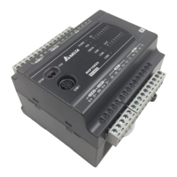
5 Temperature Measurement Module DVP04TC-E2
CR#2, 3, 4, 5: CH1 ~ CH4 input mode setting
[Explanation]
Set the working mode of the channels in the analog input module. There are 9 modes for each channel
which can be set up separately.
When you set CH1 as mode 1 (H’0001) CR#2 has to be set as H’0001. The default setting = H’0000. Take
CH1 as example:
Mode 0 (H’0000): J-type (-100°C ~1,150°C).
Mode 1 (H’0001): K-type (-100°C ~ 1,350°C).
Mode 2 (H’0002): R-type (0°C ~ 1,750°C).
Mode 3 (H’0003): S-type (0°C ~ 1,750°C).
Mode 4 (H’0004): T-type (-150°C ~ 390°C).
Mode 5 (H’0005): E-type (-150°C ~ 980°C).
Mode 6 (H’0006): N-type (-150°C ~ 1,280°C).
Mode 7 (H’0007): -80mV~+80mV
Mode-1 (H’FFFF): Channel 1 unavailable
CR#7: Temperature unit setting
[Explanation]
Select the temperature unit of average temperature and presernt temperature. (Celsius °C / Fahrenheit °F).
Default = H’0000.
Mode 0 (H’0000): Celsius °C.
Mode 1 (H’0001): Fahrenheit °F.
CR#8, 9, 10, 11: CH1 ~ CH4 average times
[Explanation]
1. The average times of the signals at CH1 ~ CH4.
2. Setup range for DVP04TC-E2: K1 ~ K100. Default = K10. If the set value exceeds K100, the value will
be set as K100; if the set value is lower than K1, the set value will be set as K1
CR#12, 13, 14, 15: Average temperature measured at CH1 ~ CH4
[Explanation]
The average temperature measured at CH1 ~ CH4 is calculated according to the average times set in CR#8
~ CR#11. Temperature unit: set in CR#7. For example, if the average times is set as K10, the contents in
CR#12 ~ CR#15 will be the average of the most recent 10 temperature signals in CH1 ~ CH4
CR#20, 21, 22, 23: Present temperature measured at CH1 ~ CH4
[Explanation]
Display the present temperature at CH1 ~ CH4. Temperature unit: set in CR#7.
CR#28, 29, 30, 31: Adjusted Offset value of CH1 ~ CH4
[Explanation]
1. Set the adjusted Offset value of CH1 ~ CH4.
2. Range: K-400~K400
3. Default setting = K0.
Definition of Offset in DVP04TC-E2:
Deviation digital value from the target temperature/voltage
Mode 0 ~ Mode 6: 1
SCALE
= 0.1°.
Equation:
Offset
X
Y
)( 1 . 0
)(
Y=Digital output, X= Measured input
Mode 7: 1
SCALE
= 80mV/8000=0.01 mV.
Equation:
Offset
V
VX
Y
)m(01.0
)m (
Y=Digital output, X= voltage input
DVP-ES2 Module Manual
-6

 Loading...