Chapter 5 CPU and Module Devices
5-41
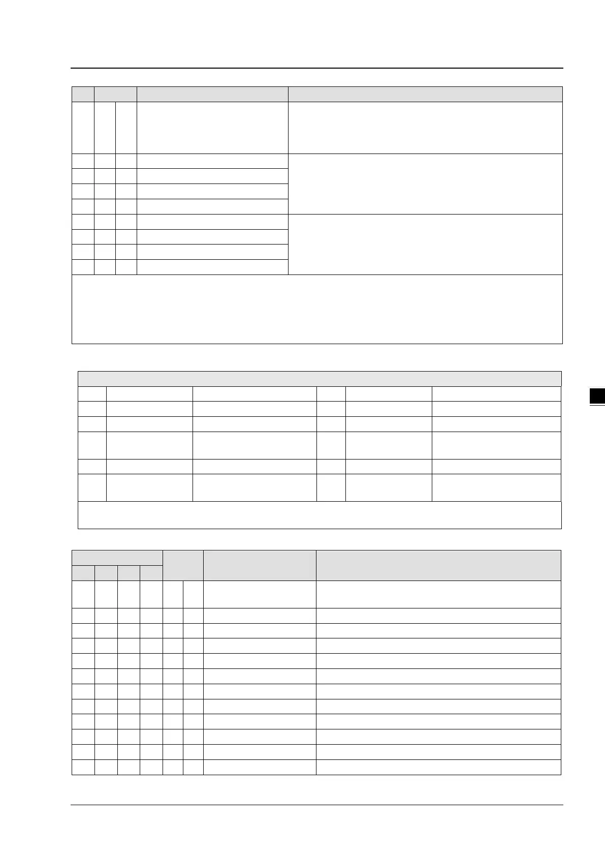
101 X R/W
Upper and lower bound status
Display the upper and lower bound status (0: Not Exceeding; 1:
Exceeding upper and lower bound value), b0~b3 corresponds to
CH1 ~ CH4 lower bound, b8~b13 corresponds to CH1 ~ CH4 upper
bound.
Set value of CH1 upper bound
Set value of CH1~CH4 upper bound. Default = K32000.
Set value of CH2 upper bound
Set value of CH3 upper bound
Set value of CH4 upper bound
Set value of CH1 lower bound
Set value of CH1~CH4 lower bound. Default = K-32000.
Set value of CH2 lower bound
110 O R/W
Set value of CH3 lower bound
Set value of CH4 lower bound
Symbols:
O: When CR#41 is set to H’5678, the set value of CR will be saved.
X: Set value will not be saved.
R: You can use FROM instruction to read data.
W: You can use TO instruction to write data.
※ CR#43: Error status value. See the table below:
bit3 K8 (H’8) CH1 Conversion error bit11 K2048 (H’0800)
Upper / lower bound setting
bit4 K16 (H’10) CH2 Conversion error bit12 K4096 (H’1000) Set value changing prohibited
bit5 K32 (H’20) CH3 Conversion error bit13 K8192 (H’2000)
Communication breakdown on
next module
Note: Each error status is determined by the corresponding bit (b0 ~ b13) and there may be more than 2 errors
occurring at the same time. 0 = normal; 1 = error
PID Control Registers
Attrib. Register content Description
120
140 160 180 O R/W
Set temperature value
Please set the temperature value according to proper range
of each sensor type. Default = K0
Range: K1 ~ K30 (s). Default = K2
P
Proportional control constant. Default = K121
I
Integral constant. Default = K2,098
D
Derivative constant. Default = K-29
Upper limit of I value. Default = K0
Lower limit of I value. Default = K0
Current accumulated offset value
128
148 168 188 O R/W
Heating/cooling 0: Heater, 1: Cooler. Default = K0
Upper limit of output. Default = K32,000
Lower limit of output. Default = K0
Output percentage (Unit: 0.1%)

 Loading...


