Communication Module DVPSCM12/52-SL
DVP-PLC Operation Manual
7
4. Control Registers (CR)
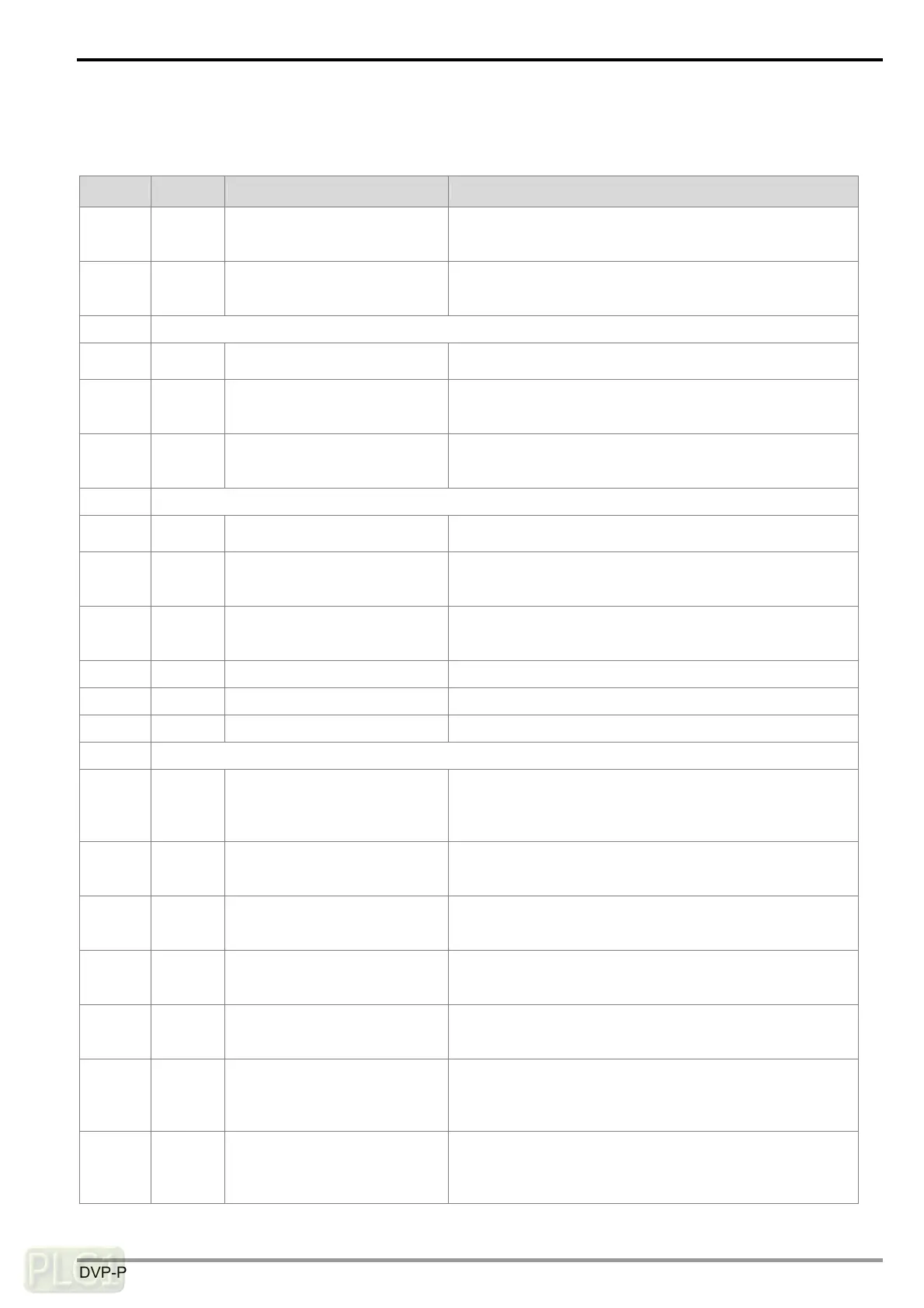
4.1 Table of Control Registers
CR# Attribute Name of the register Description
0 R Model code
The code is set up by the system.
Model code of DVPSCM12-SL=H’4041
Model code of DVPSCM52-SL=H’4042
1 R Firmware version
The firmware version is displayed in a hexadecimal value.
For example, H’0100 indicates that the firmware version is
V1.00.
2 Reserved
3 R/W
Group number triggered by
COM1 UD Link
The group number triggered by COM1 UD Link
4 R/W
Reference address of the data
senT through COM1 in UD
Link
It is used when COM1 UD Link chooses “Base+Offset”.
“Reference data register+Offset” defines the actual source
device for the data sending.
5 R/W
Reference address of the data
received through COM1 in UD
Link
It is used when COM1 UD Link chooses “Base+Offset”.
“Reference data register+Offset” defines the actual source
device for the data receiving.
6 Reserved
7 R/W
Group number triggered by
COM2 UD Link
The Group number triggered by COM2 UD Link
8 R/W
Reference address of the data
sent through COM2 in UD Link
It is used when COM2 UD Link chooses “Base+Offset”.
“Reference data register+Offset” defines the actual source
device for the data sending.
9 R/W
Reference address of the data
received through COM2 in UD
Link
It is used when COM2 UD Link chooses “Base+Offset”.
“Reference data register+Offset” defines the actual source
device for the data receiving.
10 R Module status RUN or STOP
11~19 R Error Flag The flag for an error in the module
20~27 R UD Link status The execution status of UD Link
28~29 Reserved
30 R/W
Triggering the UD Link
sequence
0: Not triggered,
1~254: Number of times the UD Link sequence is
triggered
255: Always triggered
31 R/W
Triggering the data exchange
through COM1 to read bits or
words
High byte: bit; Low byte: word
0: Not triggered; 1: Triggered once; 2: Always triggered
32 R/W
Triggering the data exchange
through COM2 to read bits or
words.
High byte: bit; Low byte: word
0: Not triggered; 1: Triggered once; 2: Always triggered
33 R/W
Triggering the data exchange
through COM1 to write bits or
words.
High byte: bit; Low byte: word
0: Not triggered; 1: Triggered once; 2: Always triggered
34 R/W
Triggering the data exchange
through COM2 to write bits or
words.
High byte: bit; Low byte: word
0: Not triggered; 1: Triggered once; 2: Always triggered
35~36 R/W
Selecting the “reading bits
through COM1” checkbox
Bit = 0: Disabling the function of reading bits through
COM1.
Bit = 1: Enabling the function of reading bits through
COM1.
37~38 R/W
Selecting the “reading words
through COM1” checkbox
Bit = 0: Disabling the function of reading words through
COM1.
Bit = 1: Enabling the function of reading words through
COM1.
 Loading...