Communication Module DVPSCM12/52-SL
DVP-PLC Operation Manual
8
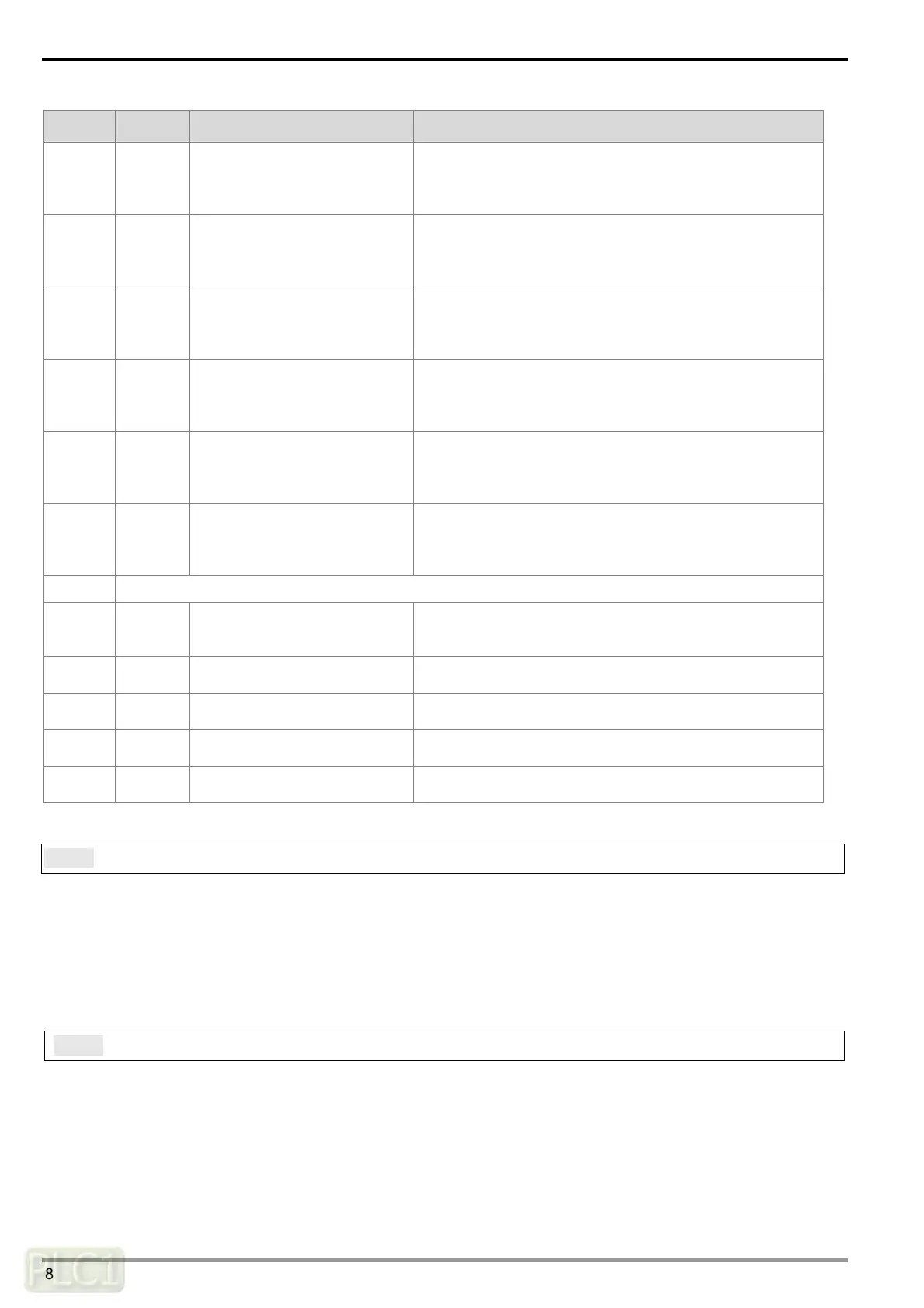
CR# Attribute Name of the register Description
39~40 R/W
Selecting the “reading bits
through COM2” checkbox
Bit = 0: Disabling the function of reading bits through
COM2.
Bit = 1: Enabling the function of reading bits through
COM2.
41~42 R/W
Selecting the “reading words
through COM2” checkbox
Bit = 0: Disabling the function of reading words through
COM2.
Bit = 1: Enabling the function of reading words through
COM1.
43~44 R/W
Selecting the “writing bits
through COM1” checkbox
Bit = 0: Disabling the function of writing bits through
COM1.
Bit = 1: Enabling the function of writing bits through
COM1.
45 ~ 46 R/W
Selecting the “writing words
through COM1” checkbox
Bit = 0: Disabling the function of writing words through
COM1.
Bit = 1: Enabling the function of writing words through
COM1.
47~48 R/W
Selecting the “writing bits
through COM2” checkbox
Bit = 0: Disabling the function of writing bits through
COM2.
Bit = 1: Enabling the function of writing bits through
COM2.
49~50 R/W
Selecting the “writing words
through COM2” checkbox
Bit = 0: Disabling the function of writing words through
COM2.
Bit = 1: Enabling the function of writing words through
COM2.
51~115 Reserved
116 R/W
Sending the MODBUS
command
1: Enabling the sending
After the sending of the MODBUS command is complete,
CR#116 is reset to 0.
117 R/W
Processing status of the
MODBUS command
0: Not yet received; 1: Processing; 2: Received; 3:
Reception failure
118 R/W
Destination of the MODBUS
command
1: COM1, 2: COM2
119 R/W
Length of the MODBUS
command
Setting the length of the MODBUS command
120~249 R/W
Contents of the MODBUS
command
The space for storing the MODBUS command which is
sent/received
4.2 Contents of Control Registers
CR#0: Model code
[Description]
1. Model code of DVPSCM12-SL=H’4041
2. Model code of DVPSCM52-SL=H’4042
3. The model code can be read out in the program to judge whether the I/O module exists.
CR#1: Firmware version
[Description]
The firmware version is displayed in a hexadecimal value, for example, H’0100 indicates that the firmware
version is V1.00.
 Loading...