Communication Module DVPSCM12/52-SL
DVP-PLC Operation Manual
40
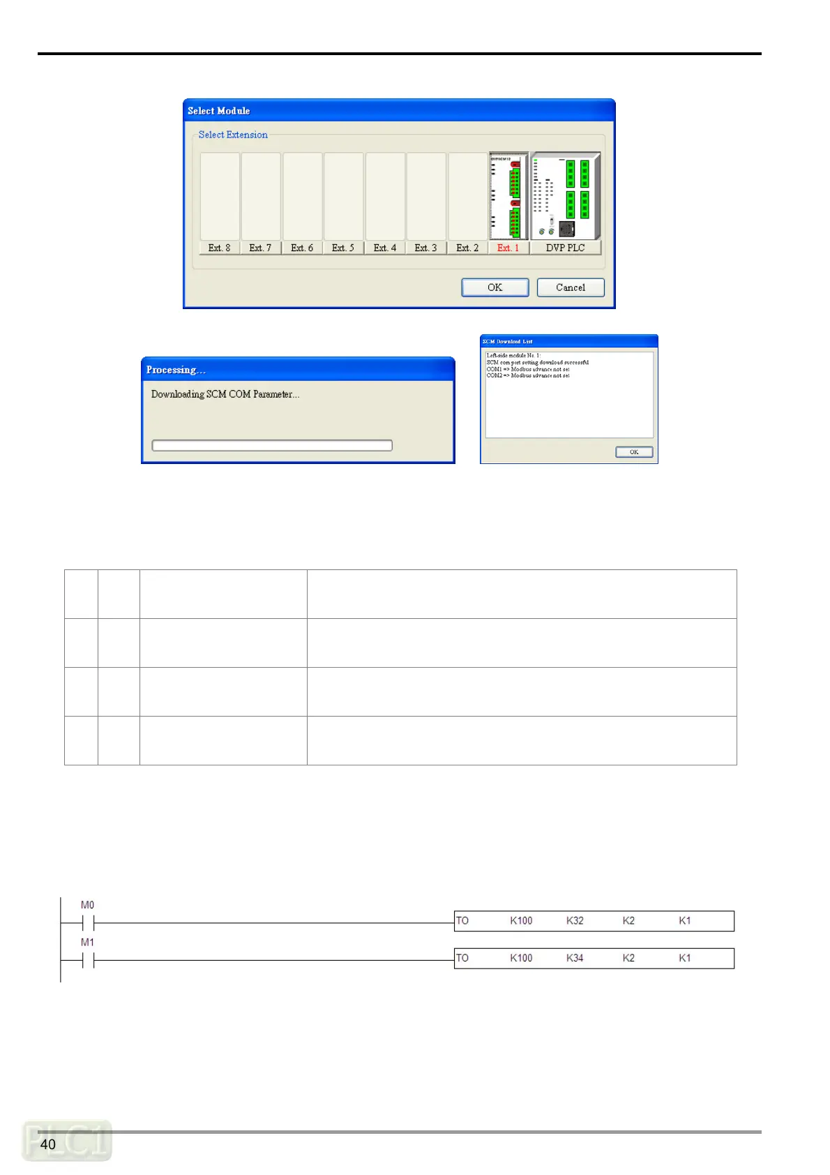
(5) Enable the data echange function.
Control the data exchange through the instruction TO in WPLSoft to read bits/read words/write
bits/write words (CR#31~CR#34).
31 R/W
Triggering the data
exchange through COM1
to read bits or words.
High byte: bit; Low byte: word
0: Not triggered, 1: Triggered once, 2: Always triggered
32 R/W
Triggering the data
exchange through COM2
to read bits or words.
High byte: bit; Low byte: word
0: Not triggered, 1: Triggered once, 2: Always triggered
33 R/W
Triggering the data
exchange through COM1
to write bits or words.
High byte: bit; Low byte: word
0: Not triggered, 1: Triggered once, 2: Always triggered
34 R/W
Triggering the data
exchange through COM2
to write bits or words.
High byte: bit; Low byte: word
0: Not triggered, 1: Triggered once, 2: Always triggered
If the user wants to keep executing the word-reading, the user can enter K2 into CR#32. If the user
wants to execute the word-reading once, the user can enter K1 intro CR#32.
If the user wants to keep executing the word-writing, the user can enter K2 into CR#34. If the user
wants to execute the word-writing once, the user can enter K1 into CR#34.
After M0 is triggered, the data will be read from the salve address which has been set through COM2
on the SCM module.
After M1 is triggered, the data will be written into the slave address which has been set through COM2
on the SCM module.