14
2. When a large number of repetitive cuts of crown moulding are required, we suggest the use of filler blocks, as
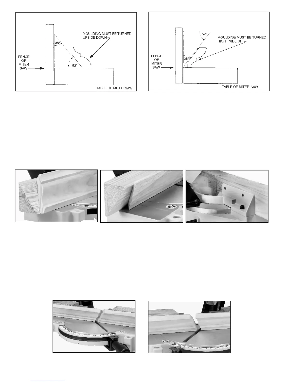
shown in Fig. 30 through Fig. 33. The majority of crown mouldings have contact surfaces at 52 and 38 degrees to the
rear surface of the moulding and these angles must be utilized when jointing the face of the filler block. For crown
mouldings with different angles, appropriate filler blocks can be produced.
3. Fig. 30 and Fig. 32 illustrate the filler block fastened to the miter saw fence with the face of the filler block extending
outward from the top of the fence and down to the surface of the table. When the filler block is positioned in this
manner, the crown moulding must be positioned on the table in the upside down position. This means that the surface
of moulding that contacts the ceiling is against the table.
4. Fig. 31 and Fig. 33 illustrate the filler block fastened to the miter saw fence with the face of the filler block extending
inward toward the fence from the top to the bottom. When the filler block is positioned in this manner, the crown
moulding is placed on the table in the same position as it would be when nailed between the ceiling and wall.
Fig. 31
Fig. 30
FILLER BLOCK FOR CROWN MOULDING IF JOINT IS TO HAVE MITERED
CORNER FIT OR COPE CUT
FILLER BLOCK FOR CROWN MOULDING IF JOINT IS TO HAVE MITERED
CORNER FIT OR COPE CUT
Fig. 32
Fig. 33
5. Fasten the filler blocks to the fence using wood screws (A) through the two holes provided on each fence half, as
shown in Fig. 34. This enables you to easily remove the filler blocks when not in use and quickly reassemble them to
the fence when needed.
6. Fig. 35 illustrates the miter saw arm in the 45 degree right miter position and the filler blocks fastened to the fence
so that the moulding will be in the same position as it would be when nailed between the ceiling and wall.
When making this cut the moulding (B) on the left of the saw blade will be for an outside corner and the moulding (C)
on the right of the saw blade will be for an inside corner.
To cut the mating pieces for mouldings (B) and (C) Fig. 35, rotate the miter saw arm to the 45 degree left miter position
and make the cut (Fig. 35). In this case the moulding (D) Fig. 36 on the left of the saw blade will be for an inside corner
and the moulding (E) on the right of the saw blade will be for an outside corner.
Fig. 34
Fig. 35
Fig. 36
B
C
D
E