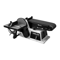
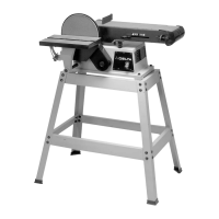
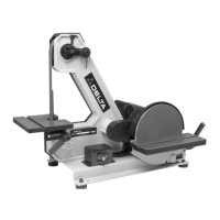
The device is a 4" Belt / 6" Disc Sander, Model SA446, from Delta's ShopMaster series. This tool is designed for sanding various materials, primarily wood, and offers versatility in its operation and setup.
Function Description:
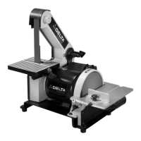
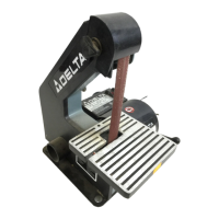
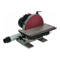
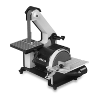
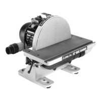
The Delta ShopMaster Model SA446 is a combination belt and disc sander. It features a 4" x 36" 60-grit sanding belt and a 6" 60-grit sanding disc. The machine is equipped with a 1/3 hp 120 Volt Single Phase Induction Motor. A key feature is its tilting table, which can be used with either the belt or disc unit. The sanding belt can be operated in horizontal, vertical, or any intermediate position, providing flexibility for different sanding tasks. The device is suitable for surfacing, edge sanding, and sanding inside and outside curves.
Important Technical Specifications:
- Model: SA446
- Motor: 1/3 hp, 120 Volt, Single Phase Induction Motor
- Sanding Belt: 4" x 36", 60-grit
- Sanding Disc: 6", 60-grit
- Table Tilt: Up to 45 degrees to the right
- Power Connection: Requires a separate electrical circuit, not less than #12 wire, protected with a 20 Amp time lag fuse. It uses a 3-prong grounding type plug.
- Extension Cords: Refer to the "MINIMUM GAUGE EXTENSION CORD" chart for recommended sizes based on ampere rating, volts, and cord length. For 0-6 Ampere Rating at 120 Volts, up to 25 feet requires 18 AWG, 25-50 feet requires 16 AWG, 50-100 feet requires 16 AWG, and 100-150 feet requires 14 AWG. For 6-10 Ampere Rating at 120 Volts, up to 25 feet requires 18 AWG, 25-50 feet requires 16 AWG, 50-100 feet requires 14 AWG, and 100-150 feet requires 12 AWG. For 10-12 Ampere Rating at 120 Volts, up to 25 feet requires 16 AWG, 25-50 feet requires 16 AWG, 50-100 feet requires 14 AWG, and 100-150 feet requires 12 AWG. For 12-16 Ampere Rating at 120 Volts, up to 25 feet requires 14 AWG, and 25-50 feet requires 12 AWG. Cords greater than 50 feet are not recommended for 12-16 Ampere Rating.
- Grounding: Must be grounded while in use to protect the operator from electric shock.
- Dimensions for Mounting: For permanent mounting, four holes are provided. The diagram shows a 15-1/2" center-to-center distance horizontally and 5-1/2" vertically between holes, with a 3/8" diameter for each hole. For mounting on a board, an 18" x 24" or larger board is recommended, with similar hole spacing.
Usage Features:
- Adjustable Belt Tension: The belt tension can be adjusted by loosening a screw, moving the sanding arm to a vertical position, and then adjusting a tensioning screw and locknut until the belt deflects approximately 1/4" under light pressure.
- Sanding Arm Position: The sanding arm can be adjusted to horizontal, vertical, or any intermediate angle by loosening a screw, positioning the arm, and then tightening the screw.
- Table Assembly: The tilting table can be mounted for use with either the belt or disc unit. When used with the sanding arm in the vertical position, the table assembly can be moved from the disc unit to the belt unit.
- Backstop Adjustment: The backstop can be adjusted to be square with the sanding belt. It should be positioned a maximum of 1/16" away from the sanding belt to prevent trapping work or fingers.
- Table Squareness with Sanding Disc: The table can be adjusted to be 90 degrees to the sanding disc using a combination square. The table lock knob allows for tilting and securing the table.
- Miter Gauge Slot Parallelism: The miter gauge slot can be adjusted to be parallel with the sanding disc by loosening screws that fasten the table to its mounting bracket and trunnion.
- Miter Gauge: A miter gauge is supplied for angle or miter sanding on the disc table. It can be rotated right or left by loosening and tightening a lock knob.
- Safety Switch: An on/off switch is located on the front of the sander. The switch toggle can be removed to lock the switch in the "OFF" position, preventing unauthorized use.
- Belt Tracking: The sanding belt's tracking can be adjusted using a tracking knob. Turning it counter-clockwise moves the belt toward the disc, and clockwise moves it away.
- Sanding Techniques:
- Surfacing/Edge Sanding: Always use the backstop. Hold the workpiece firmly, keep fingers away from the belt, and move the workpiece evenly across the belt. Apply only enough pressure to remove material.
- Inside Curves: Sanding inside curves is done with the sanding belt.
- Outside Curves: Sanding outside curves is done with the sanding disc. Always sand on the left (downward) side of the disc to avoid kickback.
- End Sanding (Belt): Use the sanding belt with the sanding arm in the vertical position and the table assembly moved to the belt unit. Use the miter gauge for accurate work.
- End Sanding (Disc): Use the sanding disc and miter gauge for narrow workpieces. Move the work from the center to the left side of the disc.
- Dust Collection: The device includes a dust chute for connecting to a dust collection system.
Maintenance Features:
- Cleaning: Periodically blow out all air passages with dry compressed air. Clean plastic parts with a soft damp cloth; avoid solvents.
- Lubrication: Apply household floor paste wax to the machine table and extension table or other work surface weekly.
- Rust Protection: To protect cast iron tables from rust, use WD-40® and a Scotch-Brite™ Blending Hand Pad with a pushblock, then degrease and apply TopCote® Aerosol.
- Belt Replacement: To replace the sanding belt, loosen the backstop, slide the tension lever to release tension, remove the old belt, and install a new one, ensuring the arrow on the belt matches the machine's travel direction. Then apply tension and replace the backstop.
- Disc Replacement: To replace the sanding disc, remove the table assembly and lower cover, peel off the old disc, clean the disc plate, and press a new sanding disc firmly into position. Then replace the cover and table assembly.
- Wrench Storage: Two holes are provided in the base casting to store the supplied hex wrenches.