Chapter 12 Description of Parameter Settings|CFP2000 Series
12.1-08-5
well. The control objects include occasions with integral component loads, which are controlled
by the P action only, and sometimes, if the integral component is functioning, the whole system
will be vibrating. On such occasions, in order to make the P action’s vibration subsiding and the
system stabilizing, the PD control could be utilized. In other words, this control is good for use
with loadings of no brake functions over the processes.
PID Control: Utilize the I action to eliminate the deviation and the D action to restrain the
vibration, thereafter, combine with the P action to construct the PID control. Use of the PID
method could obtain a control process with no deviations, high accuracies and a stable system.
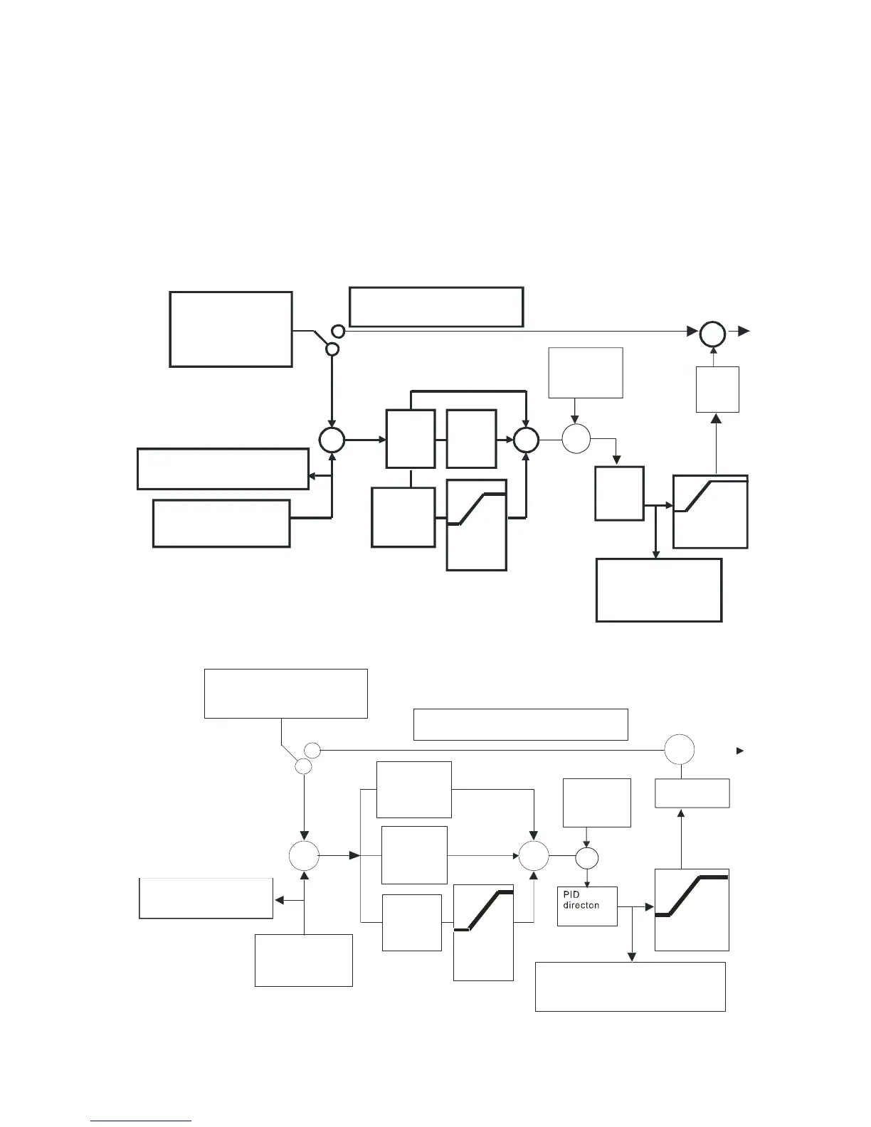
Serial connection
Input Selection
of the PID Feedback
PID Cancelled
PID Freq.
output
command
limit
08-09
Treatment of the
Feedback Signal Fault
Integral Time
Proportion
gain
00-04=10 display of the
PID feedback
Differential
Time
00-20:KPC-CC01/
RS485
03-00~02:4 PID target
value
08-00=0
or 02-01~06=21(disable)
08-00:AVI/ACI
AUI/PG
P
08-01
D
08-03
I
08-02
08-04
08-21
If Hz>08-05
time exceeds 08-08
08-05
Frequency
command
+
-
+
+
Input Selection of the
PID Target Value
1
2
08-16
PID
Compensation
Selection
Display of the PID feedback
upper limit
for
Integral
+
+
PID
direction
PID
Delay
Time
08-07
Parallel connection
Input Selection
of the PID Feedback
PID Cancelled
08-09
Treatment of the Feedback Signal Fault
00-04=10 display of the
PID feedback
08-00=0
or 02-01~06=21(disable)
08-00:AVI/ACI
AUI/PG
If Hz>08-05, time exceeds 08-08
Frequency
command
Display of the PID feedback
08-21
08-05
+
-+
+
2
08-04
I
P
08-01
1
+
D
08-03
Input Selection of the
PID Target Value
00-20:KPC-CC01/RS485
03-00~02:4 PID target value
08-02
Integral Time
Differential
Time
Proportion gain
upper limit
for
Integral
PID Freq.
output
command limit
PID Delay Time
08-07
PID
compensation
selection
08-16