Chapter 6 Control Terminals|CFP2000 Series
6-5
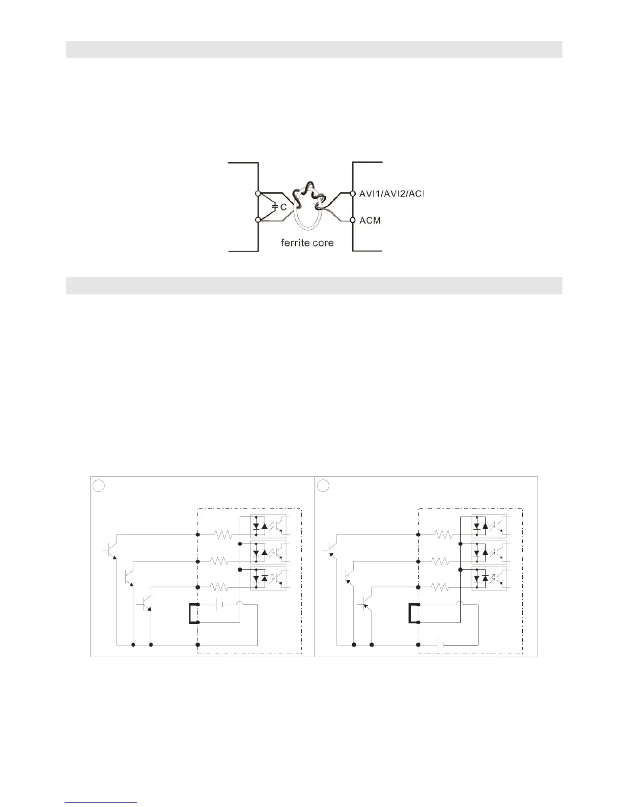
Analog input terminals (AVI1, AVI2, ACI, ACM)
; Analog input signals are easily affected by external noise. Use shielded wiring and keep it as
short as possible (<20m) with proper grounding. If the noise is inductive, connecting the shield to
terminal ACM can bring improvement.
; If the analog input signals are affected by noise from the AC motor drive, please connect a
capacitor and ferrite core as indicated in the following diagram.
Wind each wires 3 times or more around the core
Digital inputs (FWD, REV, MI1~MI8, COM)
; When using contacts or switches to control the digital inputs, please use high quality components
to avoid contact bounce.
; The “COM” terminal is the common side of the photo-coupler. Any of wiring method, the “common
point” of all photo-coupler must be the “COM”.
;
When the photo-coupler is using internal power supply, the switch connection for Sink and Source as below:
MI-DCM: Sink mode, MI-+24 V: Source mode
;
When the photo-coupler is using external power supply, remove the short circuit cable between the +24V
and COM terminals. The connection mode is Sink mode or Source mode is according to the below:
The “+” of 24V connecting to “COM: Sink mode
The “-“ of 24V connecting to COM: Source mode
1
2
DCM
MI1
+2 4V
MI2
MI8
~
COM
DCM
MI1
+2 4V
MI2
MI8
~
COM
Sink Mode Source Mode
with internal power (+24VDC)
with internal power (+24VDC)
internal circuit
internal circuit