Chapter 12 Description of Parameter SettingsMS300 (High Speed Model)
12-09-6
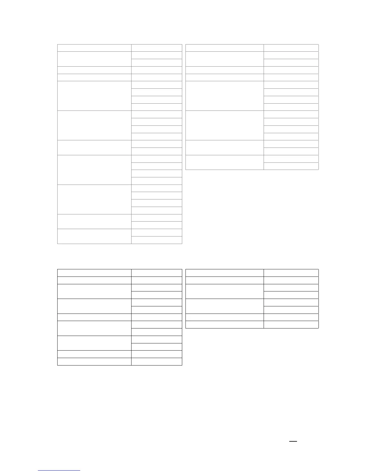
ASCII Mode
Command Message: Response Message
STX ‘:’ STX ‘:’
ADR 1
ADR 0
‘0’
ADR 1
ADR 0
‘0’
‘1’ ‘1’
CMD 1 ‘1’ CMD 1 ‘1’
CMD 0 ‘0’ CMD 0 ‘0’
Target register
‘0’
Target register
‘0’
‘5’ ‘5’
‘0’ ‘0’
‘0’ ‘0’
Number of register
(count by word)
‘0’
Number of register
(count by word)
‘0’
‘0’ ‘0’
‘0’ ‘0’
‘2’ ‘2’
Number of register
(count by Byte)
‘0’
LRC Check
‘E’
‘4’ ‘8’
The first data content
‘1’
END
CR
‘3’ LF
‘8’
‘8’
The second data content
‘0’
‘F’
‘A’
‘0’
LRC Check
‘9’
‘A’
END
CR
LF
RTU mode:
Command Message:
Response Message:
ADR 01H ADR 01H
CMD 10H CMD 1 10H
Target register
05H
Target register
05H
00H 00H
Number of register
(count by word)
00H
Number of register
(count by word)
00H
02H 02H
Quantity of data (Byte) 04 CRC Check Low 41H
The first data content
13H CRC Check High 04H
88H
The second data content
0FH
A0H
CRC Check Low ‘9’
CRC Check High ‘A’
Check sum
ASCII mode:
LRC (Longitudinal Redundancy Check) is calculated by summing up, module 256 and the values
of the bytes from ADR1 to last data character then calculating the hexadecimal representation of
the 2’s-complement negation of the sum.
For example:
01H + 03H + 21H + 02H + 00H + 02H = 29H, the 2’s-complement negation of 29H is D7H.
 Loading...


