Chapter 6 Control TerminalsMS300 (High Speed Model)
6-1
Chapter 6 Control Terminals
Analog input terminals (AVI, ACI, ACM)
Analog input signals are easily affected by external noise. Use shielded wiring and
keep it as short as possible (< 20 m) with proper grounding. If the noise is
inductive, connecting the shield to terminal ACM can bring improvement.
Use twisted-pair for weak analog signals.
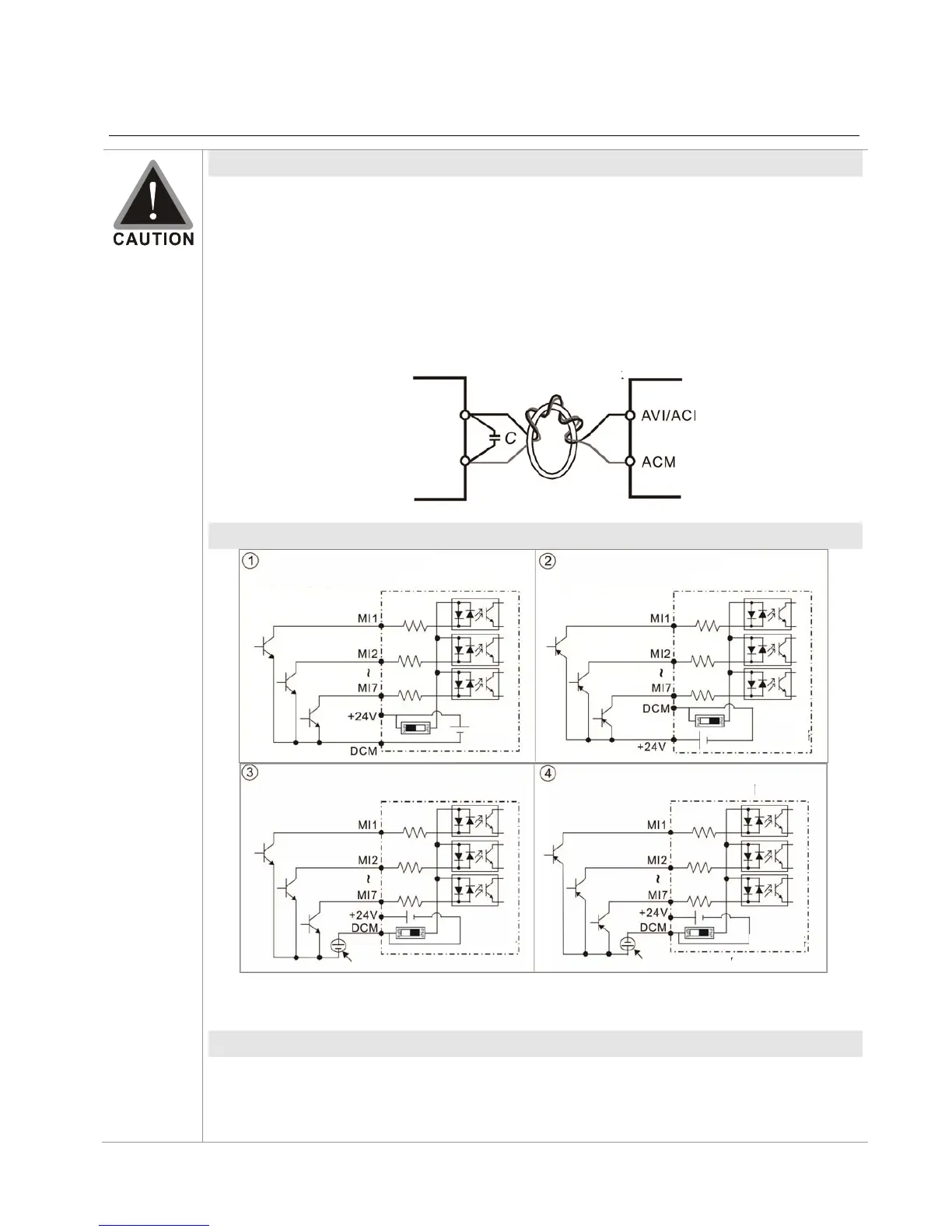
If the analog input signals are affected by noise from the drive, please connect a
capacitor and ferrite core as indicated in the following diagram.
Contact input terminals
(
MI1~MI7, DCM, +24V
)
Sink Mode
with internal power (+24Vdc)
Source Mode
with internal power (+24Vdc)
internal
circuit
internal
circuit
Sink Mode
with external power
Source Mode
with external power
internal
circuit
internal
circuit
external power + 24V external power + 24V
When the photo-coupler is using internal power supply, the switch connection for Sink
and Source as below: MI-DCM: Sink mode, MI-+24 V: Source mode
Transistor Output Terminal (MO1, MO2, MCM)
Make sure to connect the digital outputs to the right polarity, see wiring diagram
When connecting a relay to the digital output, connect a surge absorber across the
coil and check the polarity.
Ferrite core
Wind each wire 3
times or more
around the core
(+24 VDC) (+24 VDC)
 Loading...


