Chapter 16 PLC Function ApplicationsMS300 (High Speed Model)
16-100
16-8 Explanation of PLC speed mode controls
Register table for speed mode:
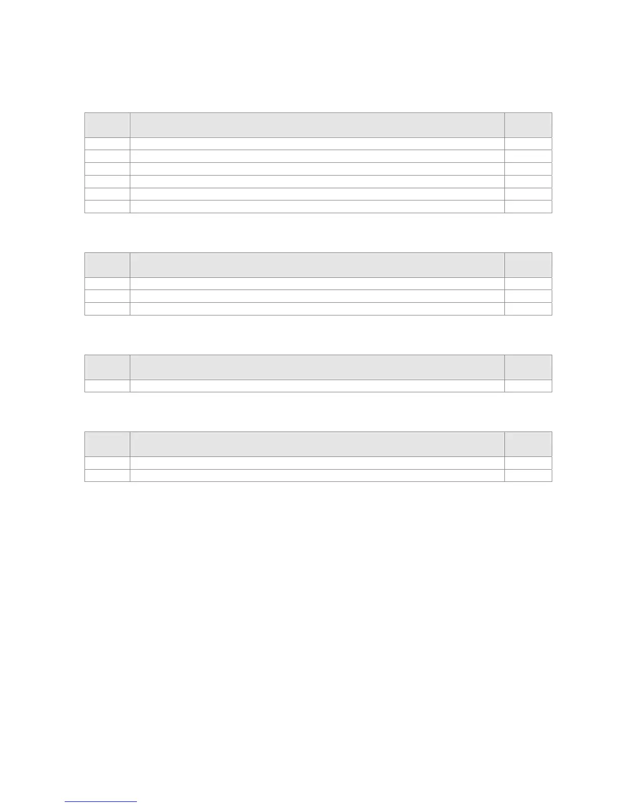
Control special M
Special
M
Description of Function
ttributes
M1025 Drive frequency = set frequency (ON) / drive frequency =0 (OFF)
RW
M1026 Drive operating direction FWD(OFF) / REV(ON)
RW
M1040 Hardware power (Servo On)
RW
M1042 Quick stop
RW
M1044 Pause (Halt)
RW
M1052 Lock frequency (lock, frequency locked at the current operating frequency)
RW
Status special M
Special
M
Description of Function
ttributes
D1037 Drive output frequency (0.0~####.#)
RO
D1050 Actual operating mode (speed mode is 0)
RO
Speed mode control commands:
FREQ(P) S1 S2 S3
Target speed The first acceleration time setting The first deceleration time setting
Example of speed mode control:
1. Setting D1060 = 0 will shift the drive to the speed mode.
2. Use the FREQ command to control frequency, acceleration time, and deceleration time.
3. Set M1040 = 1, the drive will now be excited, but the frequency will be 0.
4. Set M1025 = 1, the drive frequency command will now jump to the frequency designated
by FREQ, and acceleration/deceleration will be controlled on the basis of the acceleration
time and deceleration time specified by FREQ.
5. M1052 can be used to lock the current operating frequency.
6. M1044 can be used to temporarily pause operation, and the deceleration method will comply
with deceleration settings.
 Loading...


