5.7.4 Mobile control system
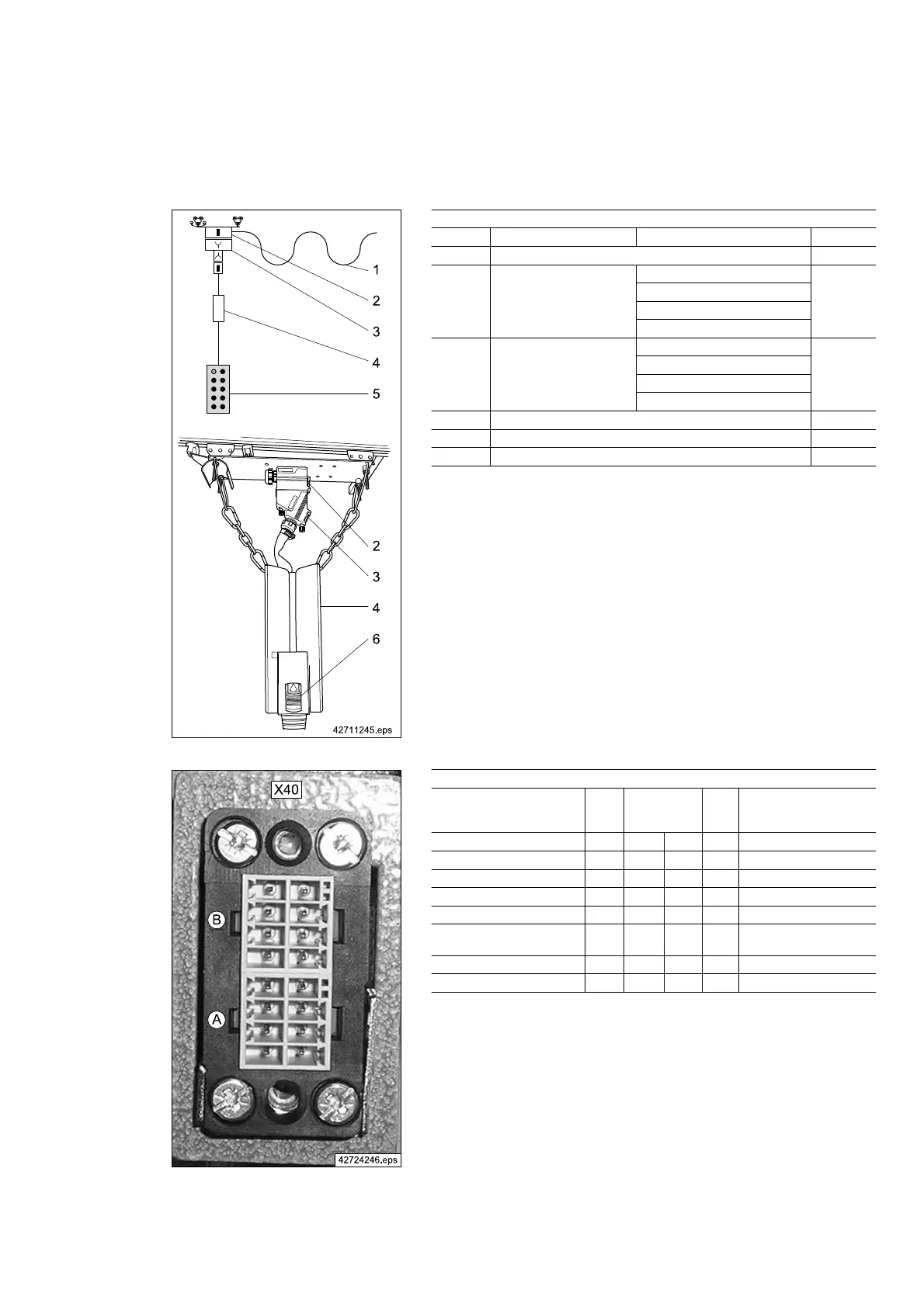
Fig. 23
Component parts
Item
Designation comprising Part no.:
1 11-pole + PE flat cable 720 139 45
2 Connector enclosure cpl.
Socket enclosure
720 187 45
Fitting frame
Pin insert VC-AMS8
Flat cable union
3 Connector adapter cpl.
Bayonet lock
720 087 45
Bush enclosure VC-MP-1-R-M25
Bush frame VC-TR1/2M
Socket insert VC-TFS8
4 Cable collector 720 065 45
5 DSE10-C control pendant 773 352 45
6 Control cable lock -
Tab. 31
For use of the cable collector, the height-adjustable standard control ca‐
bles H4, H5, H8, H11 are used.
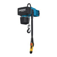
Fig. 24
X40 plug connector connections
Signal
Con‐
duc‐
tor
PIN
Con‐
duc‐
tor
Signal
- - B4 B8 11 Reference potential (24 V)
PE PE B3 B7 - -
- - B2 B6 - -
Special 2 (horn) 8 B1 B5 10 Right
Left 4 A4 A8 7 Lowering
Lifting 3 A3 A7 9
Control voltage
(24 V, STS)
Emergency stop 2 A2 A6 6 Backward
Forward 1 A1 A5 5 Special 1 (F1/F2)
Tab. 32
21480244/181209
47