Item Designation Terminal strip Function
6 Contactor On / Off
7 Transformer
8 Plug-and-socket con‐
nector
X1 Line
9 Fork light barrier Pulse generator
10 IR transmitter diode IR interface
11 7-segment LED Multi-function display, e.g.: Elapsed operating time counter, status indicator, error
code display
12 Plug-and-socket con‐
nector
X4 Lifting limit switch
13 Dummy plug X5 Trolley (optional)
14 Plug-and-socket con‐
nector
X3 Control cable
SN... Serial number
Tab. 33
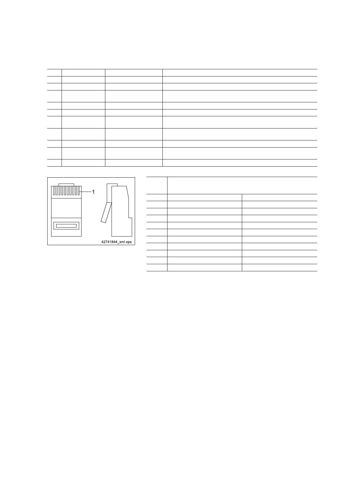
Fig. 30 Pin 1 (1)
RJ45
connec‐
tor
Function assignment
PIN
Control cable X3 (14) Trolley X5 (13)
1 Special F1 Special F1
2 Crane forward Crane forward
3 Crane Reverse Crane Reverse
4 Emergency stop Emergency stop
5 Supply control pendant Supply control pendant
6 Lifting 24 V AC from chain hoist
7 Lowering Reference potential control pendant
8 Trolley right Trolley right
9 Trolley left Trolley left
10 Special F2 Special F2
Tab. 34
54
21480244/181209