20
D-A03
GND CH1 CH2
XY
100k
470p
470p
100k
IC1201 4pin
(GND) (TP1202)
IC1201 11pin
(EOUT)
IC1201 12pin
(FOUT)
a
b
Oscilloscope
Lissajous Wave-form
(a:b=4:1 or less)
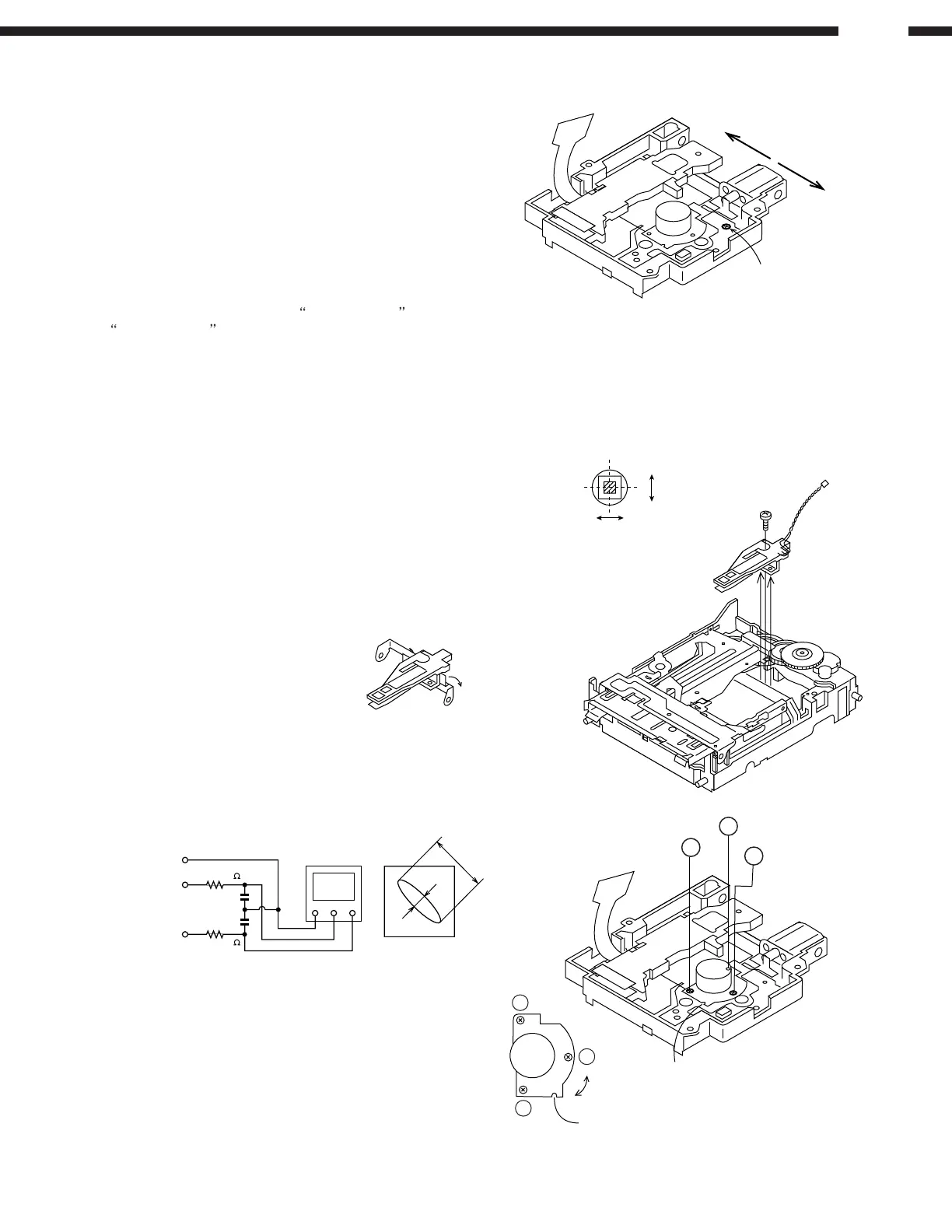
Optical Pickup Grating Deviation Measuring Method
Lower with finger
Radial Direction
Magnetic Head
Tangential Direction
Object Lens
Lead-in SW Position Measurement Mode
1. Adjustment
Load the high reflection test disc TGYS1.
Note: Adjust the lead-in switch position to FF85 ~ FFD2.
1. Loosen 1 screw (A1) fixing the Mecha. SW P.W.B.
2. Loosen the screw once and retighten it with pushing the
P.W.B. to the A direction if the lead-in switch position is
less than FF85 before loosening the screw, or with
pushing to the B direction if the position is more than
FFD2.
Then measure the lead-in switch position again, and
tighten the screw (A1) firmly if it's within the spec.
2. Confirmation
Check that the display shows
_COMPLETE_ instead of
#COMPLETE_ in step 4 of the AUTO adjustment mode.
• Rotating the loading motor forcibly
The loading motor can be rotated forcibly by rotating the VOL
UP/DOWN button while STOP or EJECT in the test mode
appears on the display
Magnetic Head Mounting Position Check
• Check the mounting position of the magnetic head
without fail when replacing the head or optical pickup.
• To adjust the mounting position easier, move the optical
pickup to the center position beforehand.
1. Load the transparent test disc for head alignment.
2. Lower the magnetic head up-shift arm manually to lift up
the magnetic head.
3. View the unit from the above and check that the object
lens of the pickup aligns with the magnetic head.
4. Check whether the magnetic head moves up or down
smoothly.
Mechanism Adjustment
• How to check optical pickup grating
Adjust the Lissajous Wave-form (x-y) of EOUT against FOUT
after performing automatic adjustment at Auto Adjust Mode
(COMPLETE indication) using the high reflection test disc.
1. Loosen 3 screws fixing the spindle motor a little, and
adjust with watching the Lissajous Wave-form.
2. Tighten the screws in the order 1, 2, and 3 after the
adjustment.
2
1
3
Adjusting
Cutout
Slide the mounting position of
the spindle motor with inserting
a screwdriver etc. in the
adjusting cutout, and check the
Lissajous Wave-form.
3
2
1
(A1) × 1
A
B