SIGNAL LINE
R805,806 2K 4.3K
E1H E3
F701 T4A/250V 4A/125V
F702 T2.5/250V 2.5/250V
E1H E3
+10V
+8V
+5.5V
+6V
8
76
5
4
3
2
1
A
B
C
D
E
D-A03
67
SCHEMATIC DIAGRAM (3/5)
SCHEMATIC DIAGRAM (3/5)
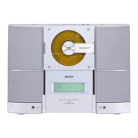
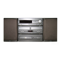
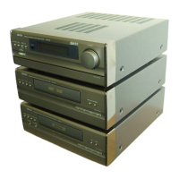
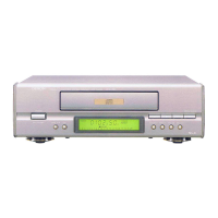
POWER/AMP P.W.B.
NOTICE
ALL RESISTANCE VALUES IN OHM. k=1,000 OHM M=1,000,000 OHM
ALL CAPACITANCE VALUES IN MICRO FARAD. P=MICRO-MICRO FARAD
EACH VOLTAGE AND CURRENT ARE MEASUERD AT MO SIGNAL INPUT
CONDITION.
CIRCUIT AND PARTS ARE SUBJECT TO CHANGE WITHOUT PRIOR
NOTICE.
WARNING:
Parts marked with this symbol have critical characteristics.
Use ONLY replacement parts recommended by the manufacture.
CAUTION:
Before returning the unit to the customer, make sure you make either (1) a
leakage current check or (2) a line to chassis resistance check. If the leakage
current exceeds 0.5 milliamps, or if the resistance from chassis to either side
of the power card is less than 460kohms, the unit is defective.
WARNING:
DO NOT return the unit to the customer until the problem is located and
corrected.