ENGLISH
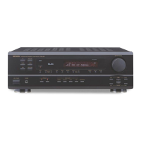
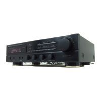
Getting Started
[
Rear]
Connections
---------------------,
VD/VDP
VCR
DBS/CABLE
TV
I
Power buttons··············
..
(20)
1---~Q
__
.92
__
Q
__
.92j
Cable indications
The hookup diagrams on the subsequent pages assume the use
of
the following optional connection
cables (not supplied).
IN
IN
OUT
OUT
Audio signal
Video signal
OUT
OUT
IN
IN
+
~r-c::
Pin-plug cable
Pin-plug cable
(White)
~
(Red)
~
+
III Analog connections (Monaural, for subwoofer)
III Analog connections (Stereo)
Ii
Speaker connections
TUNING buttons ····
..
······(14)
MEMORY button
..
··········(14)
~~----tMODE
button·
..
·
..
······(14,
18)
Number buttons
(0
- 9, +10)
··
..
·····
..
·····(14,20)
Input source selector
buttons····························
(12)
IBAND
button
·
..
····
....
····
..
·(14)
I~-"""""'--
Memory block
buttons (A -
G)
··········....·(14)
Speaker cable
=
=
=
=
=
iii
Video connections
(Yellow)
~
~_.
---;~Ia(--~
~
Video cable (75 Q/ohms video pin-plug cable)
NOTE:
• Do not plug
in
the
power
supply cord until
all
connections have been completed.
• When making connections, also refer
to
the
operating instructions
of
the other components.
• Be sure
to
connect the left and right channels properly (left
with
left, right
with
right).
• Do not bundle
power
cords together
with
speaker cables. Doing so could result
in
humming or noise.
NOTE:
• If buttons on
the
front
or rear are pressed strongly,
the
button on the opposite side will be activated
too.
6
ENGLISH
 Loading...