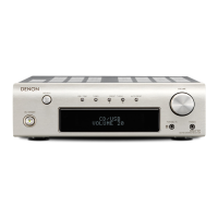
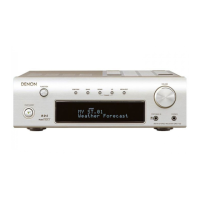
q Power operation switch
(ON/STANDBY) ····························(11, 18, 21)
w Power indicator ········································(11)
e Remote control sensor ······························(2)
r Display ·························································(3)
t PORTABLE IN jack ····································(10)
y PHONES jack
• Use this jack to connect headphones
(commercially available).
When headphones are plugged in, the sound
can only be heard from the headphones.
u VOLUME control knob·····························(11)
i MENU/SET button·····················(13, 15 ~ 23)
o TUNING buttons ······························(12 ~ 15)
!0 BAND button······························(12 ~ 15, 18)
!1 SDB/TONE button····································(11)
!2 FUNCTION knob ························(11 ~ 13, 15)
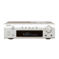
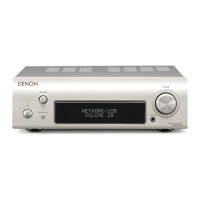
Display
q Information display
Various information is displayed here,
depending on the operation mode.
• Function
•Time
• Name of radio station
•Preset station name
•Volume level
•Tone adjustment level, etc.
w Remote control signal reception indicator
e Timer operation indicator
r Tuner reception mode indicators
t Tone indicators
• SDB:
Lights when the super dynamic bass function is
set to “ON”.
• TONE:
Lights when the tone (bass/treble) is being
adjusted.
For details on the functions of these parts, refer to the pages given in parentheses ( ).
Rear panel
q ANTENNA terminals ··································(9)
w MONO OUT terminal ·································(8)
e SYSTEM CONNECTOR jack·······················(7)
r DOCK CONTROL jack·······························(10)
t SPEAKER SYSTEM terminals····················(8)
y AC outlet ·····················································(7)
u Power supply cord ·····································(7)
i DIGITAL OPT. OUT terminal ····················(10)
o Analog input terminals······························(7)
!0 Analog output terminals ···························(7)
 Loading...