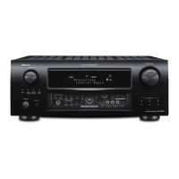
Check Power Supply Voltages for CD
CD PCB
•[IC84]:2pin 1.5V OK?
Check Reset signal for CD.
CD PCB
•[IC83]:69pin / RST "Hi" level O.K.?
Check Power Supply Voltages for CD
CD PCB
•[CN81]:4pin +12V_D
•[IC80]:IN +12V_D / OUT:+8VM
•[CN81]:2pin +3.3V
Check Oscillation waveform.
CD PCB
•[IC83]: 49pin XO
16.9344MHz OK?
Check Digital Audio Data for CODEC.
MAIN PCB
•[IC22]:37pin CD_SPDIF
OK
OK
OK
OK
OK
2.3. CD PLAY BACK
Check control signal for DIR.
MAIN PCB
•[IC22]: 23, 24, 25, 26pin
DIR_DO, DIR_DI, DIR_CLK, DIR_CE
Check the solder and replace any faulty parts.
•[IC28]: 86, 87, 88, 89pin → [IC22]:23, 24, 25, 26pin
DIR_DO, DIR_DI, DIR_CLK, DIR_CE
NG
OK
Check control signal for PWM CONTROLLER.
MAIN PCB
•[IC23]: 20, 21pin
SDA, SCL
•[IC23]: 16, 18, 19pin
RESET, PDN, MUTE
"Hi" level OK.?
END
END
Check the solder and replace any faulty parts.
•[IC28]: 82, 83pin
SDA, SCL on MAIN PCB
•[IC23]: 77, 79, 80pin A_PWM_RST, A_PWM_PDN, A_
PWM_MUTE on MAIN PCB
Check the solder and replace any faulty parts.
CD PCB
•[CN81], [IC75]
•SMPS PCB
Check the solder and replace any faulty parts.
•[IC84] on CD PCB
Check the solder and replace any faulty parts.
•[IC28]:115pin DECRST on MAIN PCB
Check the solder and replace any faulty parts.
•[X800] on CD PCB
Check the solder and replace any faulty parts.
•[IC83]:33pin CD_SPDIF on CD PCB
•[IC22]:37pin CD_SPDIF on MAIN PCB
•[WF80]:19pin CD_SPDIF
NG
NG
NG
NG
NG
NG
38
 Loading...

