LT-2023
8
TROUBLESHOOTING
SYSTEM OPERATION
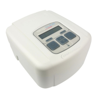
The DeVilbiss Oxygen Concentrator uses a pressure swing adsorption system. The air is drawn into the unit through air filters and into a double-head
compressor.
A pneumatic diagram of the system is shown in Figure 17.
The compressed air passes through a rotary valve (Figure 5), which is cycled at a pre-determined rate, and is directed into one of two sieve beds. The
sieve beds contain molecular sieve material which is a synthetically-produced inorganic silicate. It is very porous and has the unique ability to selectively
adsorb nitrogen from the air as it passes through the sieve bed.
As one bed is being pressurized, the other bed is quickly depressurized. This allows the nitrogen that was adsorbed during its pressurization cycle to be
exhausted from the sieve material.
The nitrogen is released through exhaust ports located on the rotary valve assembly. The ports are connected to a single piece of hose running from
the valve to the exhaust muffler.
Also during each bed pressurization, a small amount of oxygen flows through an orifice (Figure 6) from the pressurized bed into the depressurizing bed.
The orifice is clamped inside a long piece of blue tubing connecting the outlets of the two sieve beds. This helps purge the nitrogen from the
depressurizing bed.
The beds will continue to be alternately pressurized and depressurized as the unit operates.
Oxygen leaving the sieve beds is directed through a check valve to the accumulator tank. A pressure regulator (Figure 9) on the tank controls the
oxygen pressure as it leaves the accumulator and enters the flow meter. The flow meter allows the oxygen flow to be controlled and adjusted to the
level prescribed by the patient’s physician. From the flow meter the oxygen passes through the final bacteria filter (Figure 10), a check valve, and finally
the oxygen outlet port to the patient.
The DeVilbiss Oxygen Concentrator operates on a timed cycle. The cycling is controlled by the PC board. The PC board will send voltage to the valve
causing it to shift and alternately pressurize the sieve beds.
The PC board also activates the electronic alert system. A high pressure condition will be indicated with a “popping” type sound produced by release of
pressure from a pressure relief valve on the compressor head. Low flow, system abnormality, and power failure are indicated by audible and visible
alerts.
The 525 Model operating system incorporates “turn-down” technology. The PC board constantly monitors the flow rate and will decrease the cycle
time whenever the flow rate is less than 2.5 LPM. Therefore it “turns-down” the cycle based on lower oxygen demand. As a result, the unit runs cooler
and less power is consumed.
NORMAL OPERATING SEQUENCE
When the concentrator is turned “On,” the following cycling sequence can be observed by attaching pressure gauges to the sieve bed test points.
1. The rotary valve is quickly cycled several times to relieve residual bed pressure preventing a static condition in the compressor. This rapid cycling
only happens on start-up and is clearly heard as pressure is being quickly exhausted several times through the exhaust muffler that is connected to
the valve.
2. The PC board applies a short DC voltage signal to the valve. The valve will stop for several seconds causing the right bed to pressurize first while
the left bed depressurizes to approximately 2 PSI (14 kPa).
3. Voltage is again applied to the valve for a short time. The valve will stop for approximately a second. During this time the sieve bed pressures are
equalized.
4. A short DC voltage signal is again applied to the valve. The valve will stop for several seconds causing the left bed to pressurize while the right bed
depressurizes to approximately 2 PSI (14 kPa).
5. A short DC voltage signal is again applied to the valve. The valve will stop for approximately a second. During this time, the sieve bed pressures
are equalized.
6. The cycle then repeats with step 2.
NOTE–Inthe“turn-down”mode,thexedcycletimeisdecreasedtoafewsecondsandthebedpressureequalizationtimetolessthanasecond.
NOTE–High-endsievebedpressureshouldnotexceed1/2PSI(4kPa)abovehigh-endaccumulatorpressures.RefertoSpecicationsfornormal
pressures obtained during the cycle.