Control Mounting Trough
Remove top panel to access control trough. (see Removing Top Panel) It sets on the right side of the
machine and holds the control PCB’s, transformers,and pressure switch.
Main Data Communication Cable
Goes between front PCB board and Variable Frequency Drive unit mounted center rear of machine. It
has telephone type connectors at each end and is inserted at Controller PCB and the Variable Frequency
Drive.
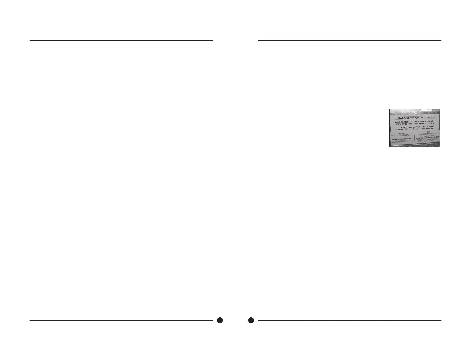
Circuit Breaker/Fuse
The fuse (optional circuit breaker) mounts to the rear channel. It carries
all of the controls in the machine but does not include the motor. To reset
the circuit breaker just push in the button. If you have a fuse then remove
fuseholder and fuse and replace with a 1 1/2 amp fast blow type fuse.
Main Control Printed Circuit Board
Please be sure to be grounded to machine before removal of this board from machine. PC board mounted
vertically behind front control panel. Remove hold down nuts in 4 corners and 1 at bottom center.
PCB Transformer Step-down
Small transformer mounted at front of control trough that is powered with 120 VAC primary and two
secondary outputs of 2.3 VAC and 24-27 VAC.
Controls Transformer
This transformer is mounted at the back of the control trough and steps a range of 208 to 240 volts down
to 120 volts for the controls. There are two terminals on the controls transformer for incoming power. One
terminal tap is marked for 208 volts use this tap for measured voltage of 200 volts - 215 volts. and the
other tap is marked 230 volts for 216 volts - 240 volts. Note: All washers have a controls transformer.
Always check the incoming voltage and use the appropriate transformer terminal when installing ALL
washers.
Main Relay Printed Circuit Board
Please be sure to be grounded to machine before removal of this board. PCB mounting horizontal in
control trough towards front of machine. Remove 4 mounting nuts.
LED Printed Circuit Board Temperature & Start Display/Push-Button
The selector switch is mounted in the center of the control panel and is held in place with ve nuts. It
allows the selection of hot, warm or cold water temperatures. Note: Do not over tighten on reinstallation as
the switch can be damaged, stay pushed in and will cause erratic displays.
Fuse Location
64
Part # 8533-053-001 REV 4/09
 Loading...