Do you have a question about the Dexter Laundry T900 and is the answer not in the manual?
Explains hazard symbols, safety terms, and warnings for safe operation.
Provides essential safety precautions and warnings for operating and servicing the washer.
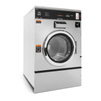
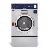
Outlines technical specifications for T-900 and T-1200 models.
Details concrete pedestal mounting and floor outline for T-900.
Details concrete pedestal mounting and floor outline for T-1200.
Covers foundation, mounting, plumbing, electrical, and drain requirements.
Explains emergency stop, door lock, and basic operating instructions.
Provides recommended detergent quantities for different washer models.
Introduces DexterLive for remote machine management, pricing, and programming.
Details how to access and navigate the manual programming menus on the washer.
Outlines the main programming menu options and sub-menus for customization.
Covers selection of test cycles, error logs, and special cycle options.
Covers setting vend prices, temp pricing, and cycle pricing for revenue management.
Details programming for plus cycles and general machine settings.
Covers machine usage tracking and control system information.
Lists common symptoms, probable causes, and suggested remedies for washer issues.
Details machine fault codes displayed on the front panel and customer actions.
Provides resistance values for motor windings for diagnostic purposes.
Step-by-step instructions for removing top, front, and back panels.
Guides on accessing and cleaning the drain valve assembly.
Details access and removal of the detergent dispenser and front soap box.
Explains the vacuum breaker and water valves for service.
Explains the door lock mechanism, access, and adjustment procedures.
Guides on adjusting, removing, and hinging the loading door.
Instructions for disassembling and reassembling the loading door.
Covers decal removal and re-installation on the control panel.
Step-by-step guide for removing the outer cabinet.
Details the door lock gear motor, thermoactuators, and their function.
Instructions for removing and replacing the drive belt.
Guides on removing and installing the cylinder and bearing housing.
Instructions for replacing water seals and removing the outer tub.
Step-by-step instructions for reassembling the cylinder.
Lists torque specifications for various bolts used in T-900, T-950, and T-1200 models.
Details the control trough, cables, breakers, PCBs, transformers, and display.
Explains emergency stop, power connection, and the Variable Frequency Drive (VFD).
Compares mechanical switches to electronic sensors and details pressure sensor adjustment.
Explains VFD motor leads, braking resistors, and cooling fan.
Illustrates electrical paths and circuits for start, fill, wash, drain, and rinse.
Details electrical circuits for wash, drain, rinse, final rinse, and spin.
Explains circuits for unlocking the door and ending the cycle.
Provides electrical schematics and wiring diagrams for T900/T1200 208-240V models.
Lists optional accessories and wiring harness part numbers.
Lists part numbers for cabinet and front panel components.
Lists parts for the front-mounted detergent dispenser.
Identifies parts accessible from the rear of the machine.
Lists part numbers for cylinder, seals, and bearings.
Details parts for the door lock assembly and gear motor.
Provides part numbers for the large door and associated hinge group.
Details parts for water inlet valves, including breakdown.
Lists part numbers for the drain valve group.
Identifies parts related to the chassis and drain system.
Lists and illustrates electrical components located in the top compartment.
Provides part numbers for control panel components.
Lists various labels and diagrams for the machine.
Details the optical coin acceptor and its components.
Provides information on the electronic acceptor conversion kit.
Explains how to set switches on the electronic coin acceptor.
Illustrates switch settings for different countries and currencies for coin acceptors.
Guides on cleaning and maintaining the electronic coin selector.
Lists electrical components for 50Hz models, including transformers.
Lists parts for the 50Hz drain valve group.
Provides part numbers for the 50Hz door lock motor assembly.
Provides electrical schematics and wiring diagrams for 50Hz models.
Outlines daily, monthly, quarterly, biannually, and annually maintenance tasks.
| Brand | Dexter Laundry |
|---|---|
| Model | T900 |
| Category | Washer |
| Language | English |