www.dfi .com
14
Chapter 2 Hardware Installation
Chapter 2
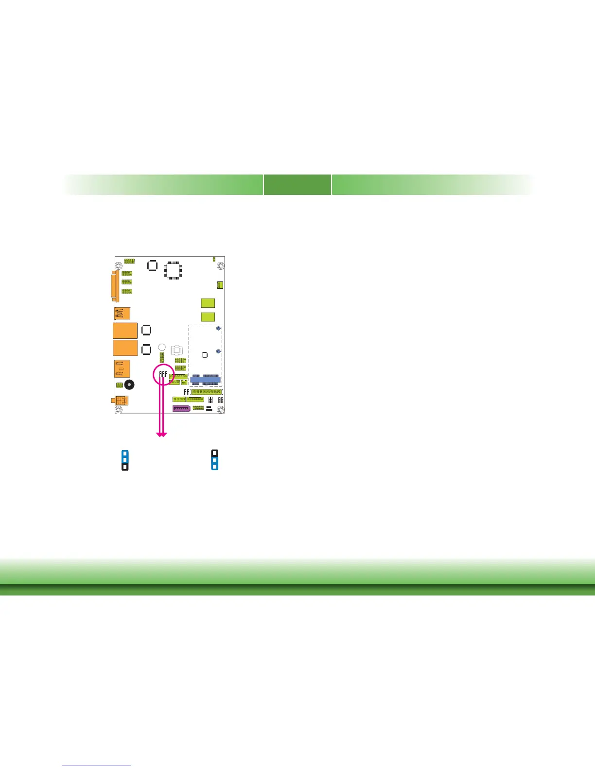
Digital I/O Output State
Based on the power level of DIO (Digital I/O) selected on JP3, JP1 (DIO pin 0-3) and JP2
(DIO pin 4-7) are used to select the output state of Digital I/O: pull high or pull low. When
selecting pull high, the power selection will be the same as the JP3’s setting.
DIO 0-3
(JP1)
DIO 4-7
(JP2)
1-2 On: +5V or +5V_standby
(default)
2-3 On: GND
3
1
2
3
1
2