Celeris User Manual
14770-A || ECN # 844 || ECN Date: 28 July 2017 Page 6 of 23
Power
Power requirement: 110 V 0- 240 V AC, 50/60 Hz
Rating: Input 85 – 264 V AC, 50/60 Hz
Power consumption in use: 24 W
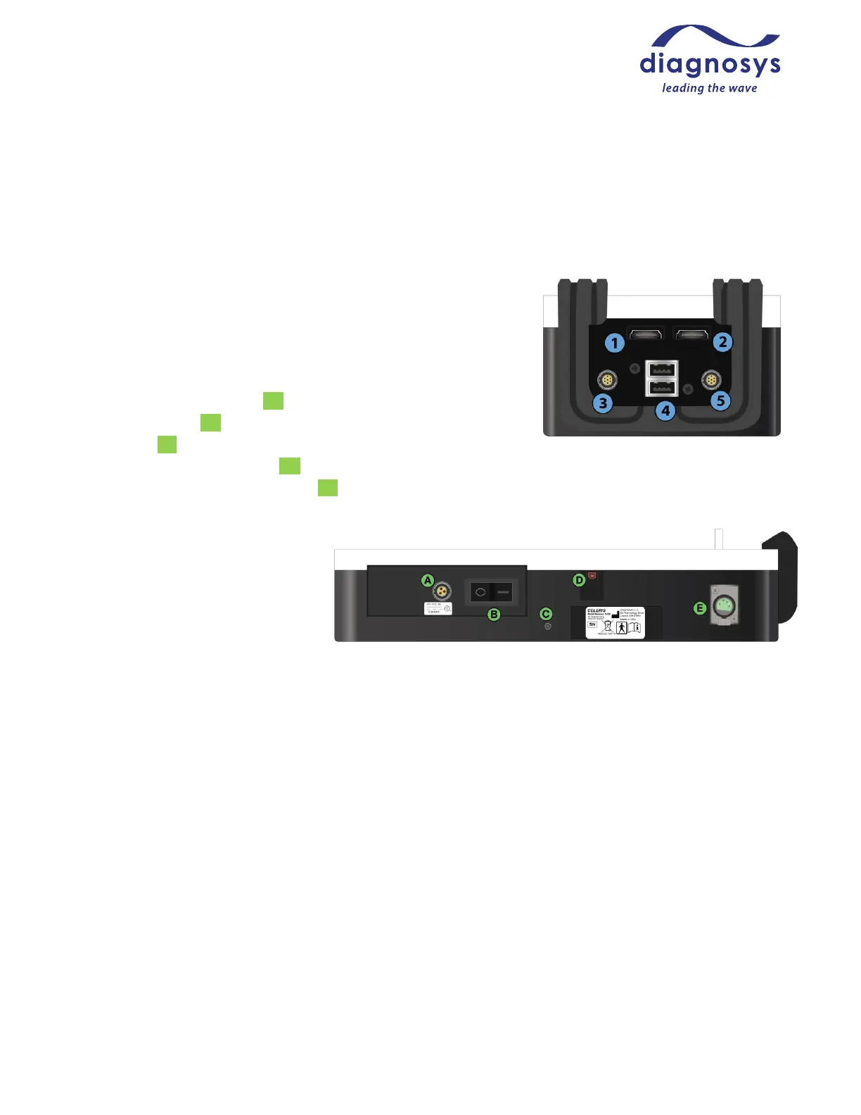
Input/Output Jacks, Power Button
Custom HDMI-connector pattern generator ports x2 (①,②)
Proprietary Ultimate 7-pin Full-field Stimulator jacks x2 (③,⑤)
USB-A power-only output jacks x2 (④)
Proprietary 12V power input (A)
Main power button (B)
Ground port (C)
High-speed (USB2.0) USB-B I/O (D)
DIN4 jack for gooseneck red LED light (E)
Output rating:
USB 1: 5V, 500 mA MAX
USB 2: 5V, 500 mA MAX
DIN4: 12V, .61A MAX
Operating Environment
The system is designed to be operated in a research laboratory under normal ambient temperature and
humidity conditions.
Although no special electrical shielding is required, the Celeris should not be placed in an electrically noisy
environment; large machinery such as cage washers, heavy-duty refrigeration equipment, or elevator motors
may introduce electrical interference into the signal.
You will need all other facilities normally required for visual electrophysiology testing, such as access to running
water and the ability to control room lighting.