DA16600 FreeRTOS Getting Started with EVK
© 2021 Dialog Semiconductor
6 Current Measurement
For detailed information on Sleep mode, see the Low Power Operation Mode section in DA16200
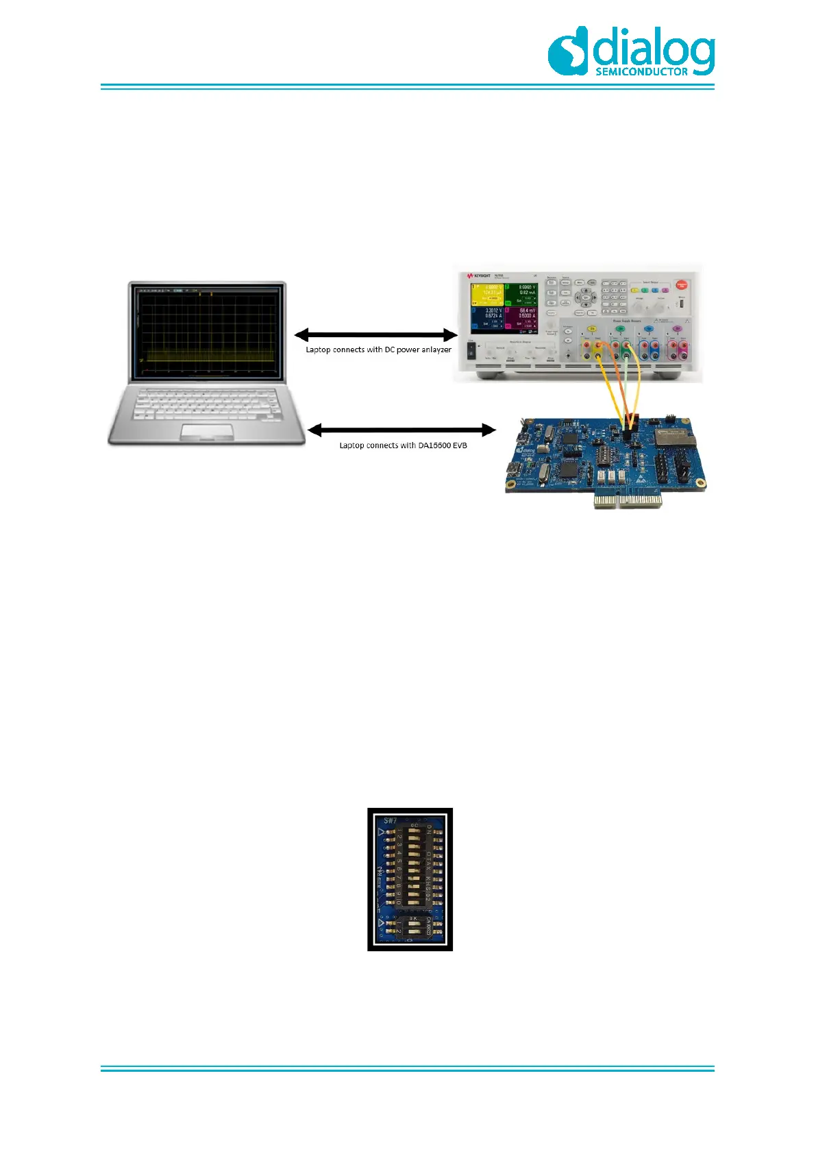
Datasheet [1]. To measure current waveform, connect the EVK's current measurement point (P1 and
P2) with the measurement instrument (KEYSIGHT 14585A).
Figure 10 shows a typical test setup environment.
Figure 10: Current Test Environment
For more details on using power meter kit, see DA16600_SB_Power_Meter_Kit_User_Manual [1].
7 Hardware Setup for RF Test
DA16600MOD consists of DA16200 and DA14531 chipsets, see chipset GUI guides for details:
● UM-WI-004 DA16200 AT GUI Tool User Manual
● AN-B-077 DA14531 Bluetooth Direct Test Mode v1.0
7.1 Wi-Fi Test Setup
GPIOA4 and GPIOA5 can be used with UART to test RF performance of DA16200.
Turn on Pin7 and 8 of SW7 to use UART with GPIOA4 and GPIOA5.
Figure 11: SW3 and SW7 Set to Use AT-GUI