DA16600 FreeRTOS Getting Started with EVK
© 2021 Dialog Semiconductor
11. Switch SW3: a switch to connect directly to DA14531 and use UART to check Bluetooth
®
LE
performance.
○ This switch is set to Off in normal operation
12. Switch SW4: a switch to control RF switch in DA16600MOD at test mode.
13. Switch SW5: a switch to check current consumption using power meter kit.
14. Switch SW7: a multipurpose switch.
○ This switch is set to Off in normal operation
15. Button S1: WPS button using GPIOA6.
○ Set to ON at Pin1 of SW7 to use this switch
16. Button S2: factory reset button using GPIOA7.
○ Set to ON at Pin2 of SW7 to use this switch
17. Button S3: reset button of DA14531 in test mode.
18. Connector J2: GPIO connector.
19. Connector J14: GPIO connector.
4.1 Description of the Switch
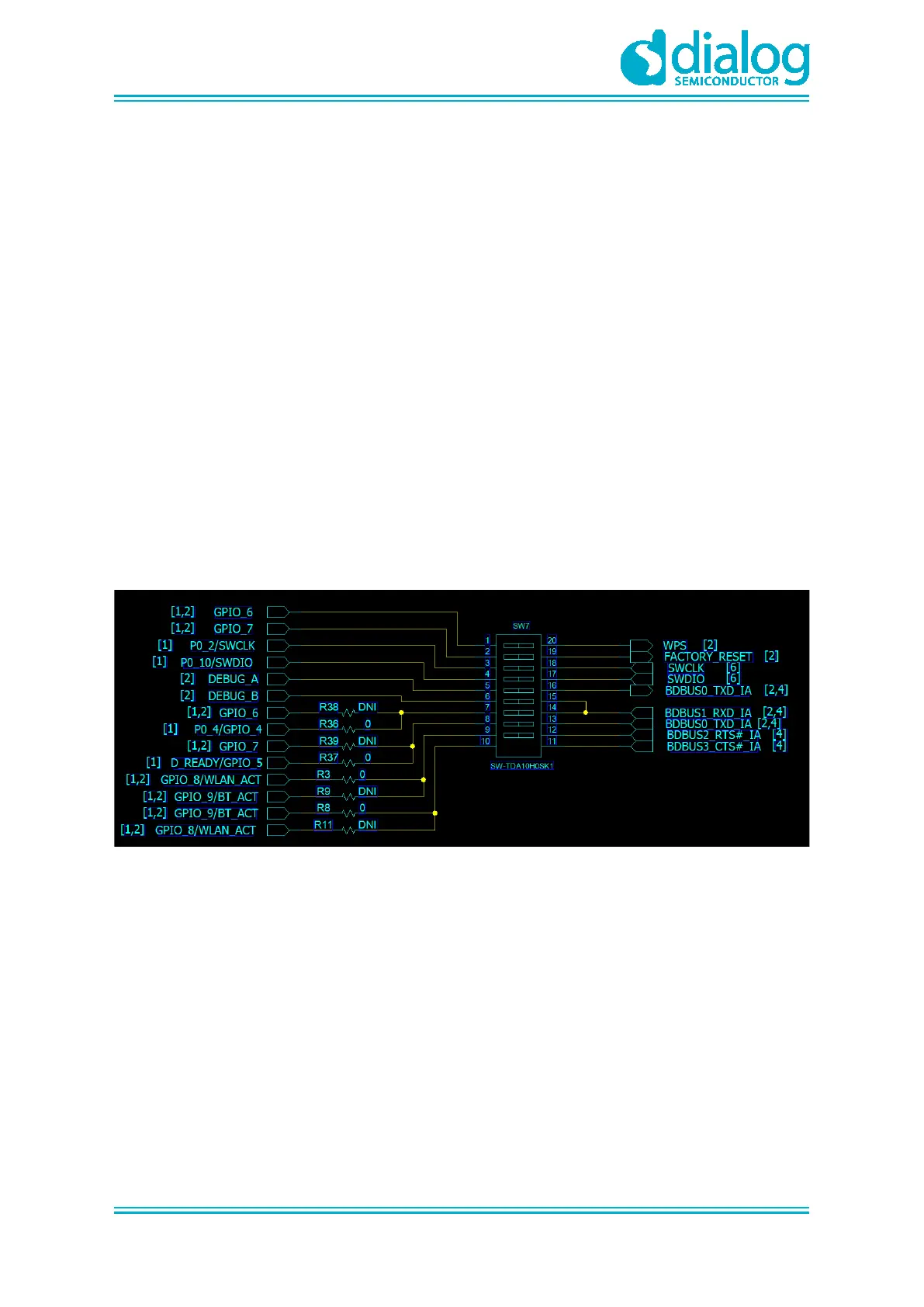
4.1.1 SW7 Pins Setting
Figure 3: The SW7 Pins
● Pin1: to use the WPS function with GPIOA_6, turn on this pin to connect S1
● Pin2: to use the Factory reset function with GPIOA_7, turn on this pin to connect S2
● Pin3,4: to debug DA14531 with Keil
● Pin5,6: to check a debug message of DA14531 in the example application
● Pin7,8: to use UART1 of DA16200 with GPIOA_4,5