DA16600 FreeRTOS Getting Started with EVK
© 2021 Dialog Semiconductor
4 DA16600 Module EVK
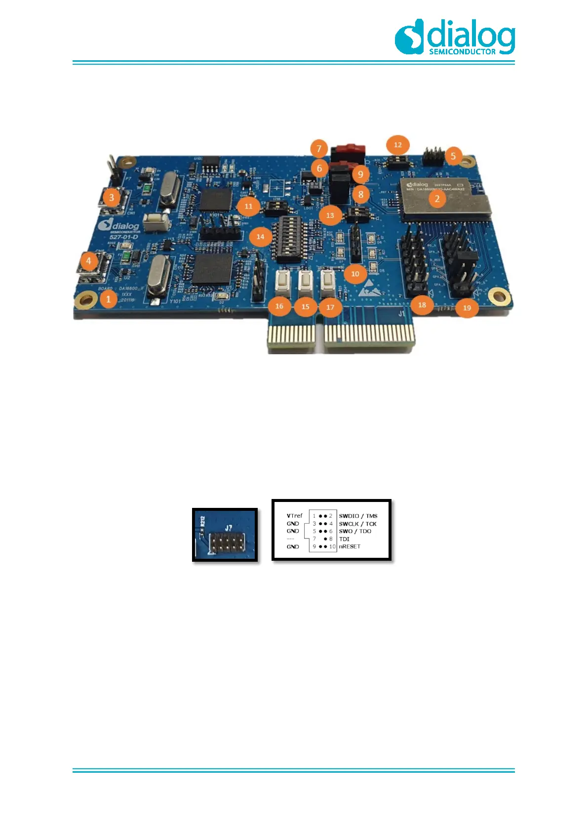
Figure 1 shows the hardware configuration of the DA16600 Module Evaluation Kit (EVK).
Figure 1: Hardware Configuration
DA16600 EVB has the following components:
1. Main board: DA16600 module (DA16600MOD-AAC) is installed.
2. DA16600MOD-AAC Wi-Fi & Bluetooth
®
LE Combo Module.
3. USB Port: UART0 is for debug, UART1 is for test.
4. USB Port: to debug, connect directly to DA14531, but do not use this port for normal operation.
5. JTAG PIN: allows connecting to I-jet (a JTAG debugger from IAR). See Figure 2.
○ Pin 7 is keyed with a white plug, so Pin 7 should be removed on EVK
Figure 2: JTAG Pin Connection
6. RTC Wake up2 key: a switch to wake up the board from Sleep Mode.
7. RTC Power key: a switch to turn On/Off the board.
8. Pin (P1): a jumper to measure current at Bluetooth
®
LE part. For normal operation, this pin
should be shorted.
○ Pull out the Short Pin cap and connect the jumper wire to measuring equipment
9. Pin (P2): a jumper to measure current at Wi-Fi part. For normal operation, this pin should be
shorted.
○ Pull out the Short Pin cap and connect the jumper wire to measuring equipment
10. Connector CN4: GPIO test purpose connector.
○ To test GPIO in J2 and J14, connect to LED by this connector