20
2
6"x6"
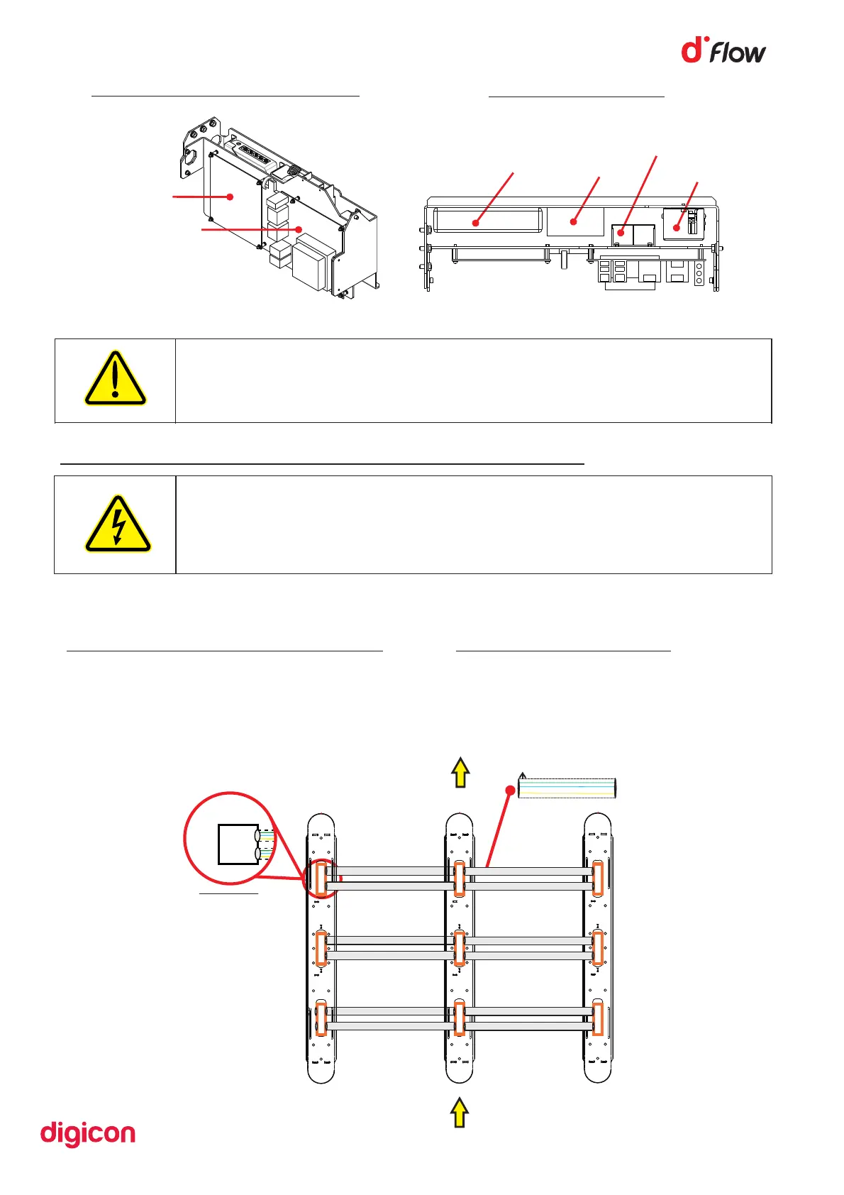
Figure 12
Panel viewed from the front
Control board
CPU
Figure 10
Switch
5V supply
CPU supply
12V supply
Figure 11
Top view of panel:
6.4 Connections between equipment
The connection cables are located on the dFlow Receiver and must pass through
the ducts as below:
Communication cable connector duct
• 037.12.377
• 037.12.378
• 037.12.379
• 037.12.380
AC Cable Connector Duct
• 037.12.376
Cableway Cableway
Cableway Cableway
Cableway Cableway
PASSAGE BOXES
50 mm diameter duct
Exit
Passage 1
Passage
WARNING
To reduce risk of electric shock, before servicing, turn off the
equipment's electrical power by switching the circuit breaker to the
OFF position. Refer all servicing to qualified service personnel only.
CAUTION
Risk of explosion if battery is replaced by an incorrect type.
Dispose of used batteries according to national and local instructions.