© 2019 Digitrax, Inc. www.digitrax.com
24
24
LOCONET
A B
USB
R
JUM P 1
GROUN D
RAI L B
JUM P 2
PRO G A
RAI L A
PRO G B
RESET
DC IN:
from PS314
13.8V / 3A
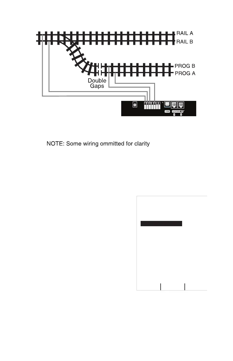
DCS52 Command Station
Programming Track
(Powered by DCS52 PROG A & B Outputs)
Main Layout (Powered by DCS52 RAIL A & B Outputs)
Programming Track Example Diagram
11.2 Using Quick Decoder Setup
Be sure that only the locomotive you want to program is on the programming
track if you use Direct, Paged or Physical CV programming.
1. To enter Quick Decoder Setup, press the Menu Key. Main Menu A will
display giving you a list of menu options. Select 1-Quick Decoder Setup
by pressing the 1 key on the keypad.
2. This will put you in Quick Decoder
Setup. Quick Decoder Setup uses Direct
Programming mode on the program track.
In Quick Decoder Setup you can change
the locomotive address and CV29 settings.
3. Once in the Quick decoder setup menu
you can change AD2 and AD4. You must
decide what address you want to use, for
addresses 0000-0127 you must use AD2.
For addresses 0128-9983 you must use
AD4.
4. Press the A Soft Key “READ” to read the
current data from your decoder. This step
isn’t required but is useful in conrming existing decoder settings.
5. To set AD2 press the 1 key on the keypad to highlight the AD2 line. Press
the C Soft Key “DATA” to select the line. Use the keypad to enter the
address you want to use, press B Soft Key “WRITE” to write the address
to the decoder. To make changes to AD4 or CV29 press the C Soft Key
“SELECT” to select additional lines in the Quick Decoder Setup Menu. If
you are done making changes press the Exit/Stop Key.
Quick Decoder Setup
0- Last Menu
1- AD2 ShortAdr
2- AD4 Long Adr
3- CV29 Value
9-
4- NDOT Rev
5- 28 not 14 Step
6- Analog
7- Speed Table
8- Use AD4
=
Pd Mode
==
=
OFF
ON
ON
OFF
ON
Trk USB Ln
READ
WRITE DATA