27
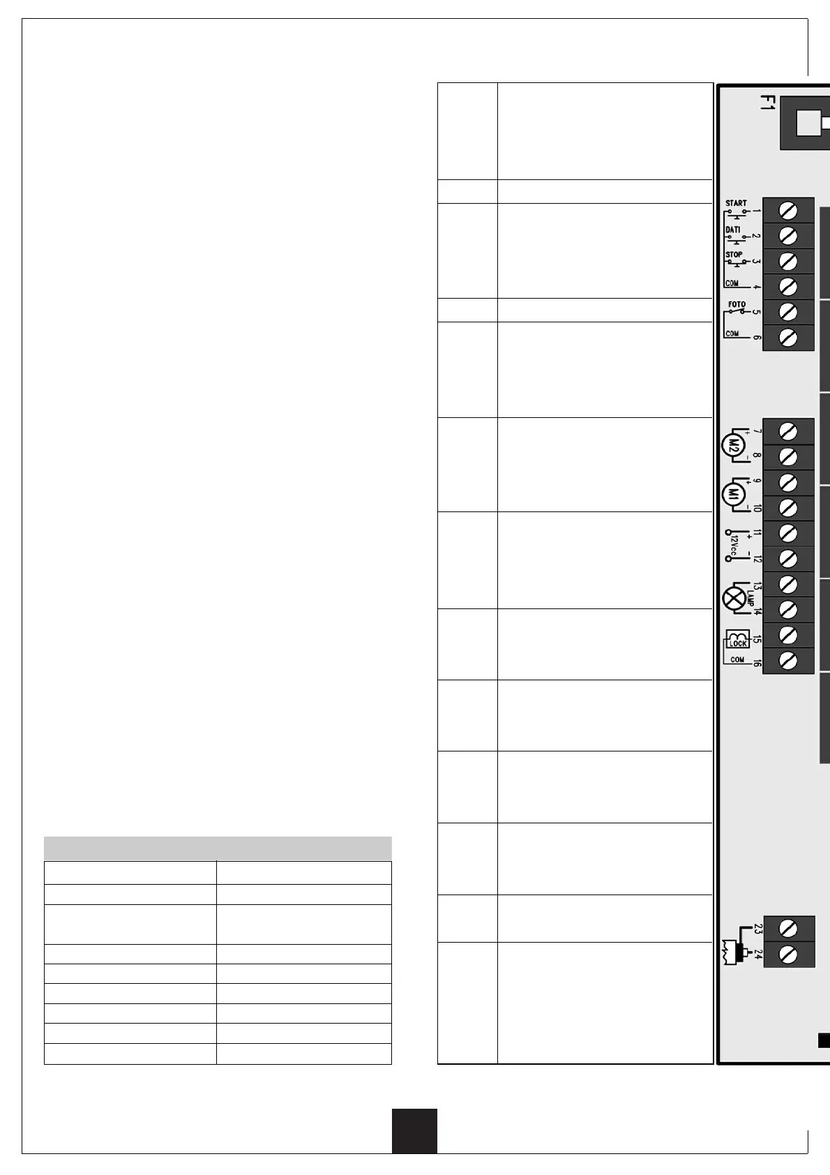
TERMINAL CONNECTIONS
1 - 4
2
3 - 4
4
5 - 6
7 - 8
9 - 10
11 - 12
13 - 14
15 - 16
17 - 18 -
19 - 20 -
21 - 22
23
24
Connect to the START button/s
(it deals with a normal open or nor-
mal closed contact, which can be
programmed by means of switch 5)
UNUSED
Connect to the STOP button
(it deals with a normal closed
contact). If it is not used make a
jumper with the common contact.
COMMON
Connect to the normal closed
contact of the PHOTOCELL. If it is
not used make a jumper with the
common contact.
Connect to the motor 2 according
to the silk screen printing polari-
ties. DO NOT use this output if it
deals with a one-door gate.
Connect to the motor 1 according
to the silk screen printing polari-
ties. Use this output if it deals
with a one-door gate.
Output for the feeding of the
PHOTOCELL). Voltage 12 VDC,
500 mA max. current.
Connect to the signaling blinking
lamp.
Voltage: 12 Volt, lamp: 10 W.
Connect to an electric lock.
Voltage: 12 VDC, 3 A max.
current.
UNUSED
Connect to the antenna cable
shielding.
Connect to the antenna cable cen-
tral connector. Use an antenna
having a 433 MHz rated frequency.
Alternatively, connect a conductor
having a 17cm main insulation.
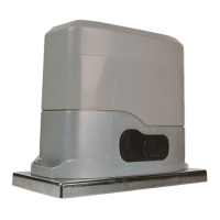
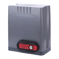
DESCRIPTION OF THE CONTROL UNIT
PRG12PP has been planned to control double- and one
– door gates, driven by means of 12V D.C. actuators.
Benefits resulting from the very low voltage
automations using PRG12PP are as follows:
• No risk of accidental electrification of the metallic
masses which are connected to the power plant
(actuators, doors and accessories).
• Anti-squashing safety, carried out by means of a
stress detector on the motor ensuring the door
movement stop in case the photocells do not detect
the presence of an obstacle.
• No blackout function by means of a lead accumulator
enabling the system operation even if no power is
supplied.
• Door slowing down in the end of stroke area, to
prevent noisy closings and door recoil.
•Time machine auto-learning: during the program
phase, the system carries out a recording cycle
concerning the door opening and closing times, so
simplifying the calibration and adjustment
operations.
The terminal inlets are equipped with the following
components:
• Infrared bearing inlet (PHOTOCELLS).
• Stop button inlet (STOP).
• Opening button inlet (START).
The terminal outputs are equipped with as follows:
• Motor 1 and Motor 2 feeding.
• 12 Volt blinking lamp (max 10 W).
• 12 Volt D.C. accessory feeding.
• 12 Volt D.C. electrolock.
Built-in super-heterodyne 433 Mhz receiver.
This system can record up to 48 Personal Pass
transmitters.
Power supply 230 VAC, 50 Hz
Motors maximum load 60 W
24VAC attachment 10 W
maximum load
Room work temperature -20 ÷ +60 °C
Fuses F1 = 2 A
F2 = 10 A
Dimensions 210 x 275 x 100 mm
Weight 2,5 Kg
Protection IP55
SPECIFICATIONS