10 www.dimplex.com
Figure 7
Fireplace Installation
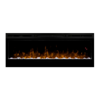
9. Replace removed junction
box cover with the supplied
hard-wire cover replacement
(Figure 7) and install using
screws removed in step 2.
10. Leaving a minimum of 3 in.
(7.6 cm) of slack, route the
power supply through the hole
in the alternate junction box
cover and secure with a wire
clamp (not supplied).
11. Connect the black wire (live)
from the unit to the black wire
from the power supply using
one of the wire connectors
removed in step 5 (Figure 5).
12. Connect the white wire (neu-
tral) from the unit to the white
wire from the power supply us-
ing the second wire connector
from step 5 (Figure 5).
13. Attach green grounding wire
to hard wire cover cover with
provided grounding screw.
Place wire in-between screw
and lock washer and tighten.
14. Reposition the electrical box
cover over the wires and con-
nectors and attach to re-
place chassis using the screw
removed in step 3.
15. Carefully reinsert partially
reective glass into replace
forward and lift off. (Figure 3)
4. Remove the 4 screws that
fasten the acrylic media tray
and the 2 screws that attach
the metal tray to the unit. The
metal tray cannot be removed
but will now allow the ability to
remove the electrical box.
5. Remove the Phillips screw to
release the electrical box cov-
er in the bottom, right corner of
the replace (Figure 5).
6. Carefully slide the electrical
box to the right to release the
securing tabs, as wires are fed
through the strain reliefs on
the cover and are connected
within.
7. Unscrew the two wire connec-
tors inside the electrical box
and separate the wires (Figure
6).
8. Pull the junction box and
power cord out the front of the
replace.
Hole for
Ground Screw