10 www.dimplex.com
Fireplace Installation
(3 wires total) for the incoming
power supply.
CAUTION: Use the appropri-
ate wire to meet local and
national electrical codes for
rated power consumption.
• Cut the wire to an appropriate
length.
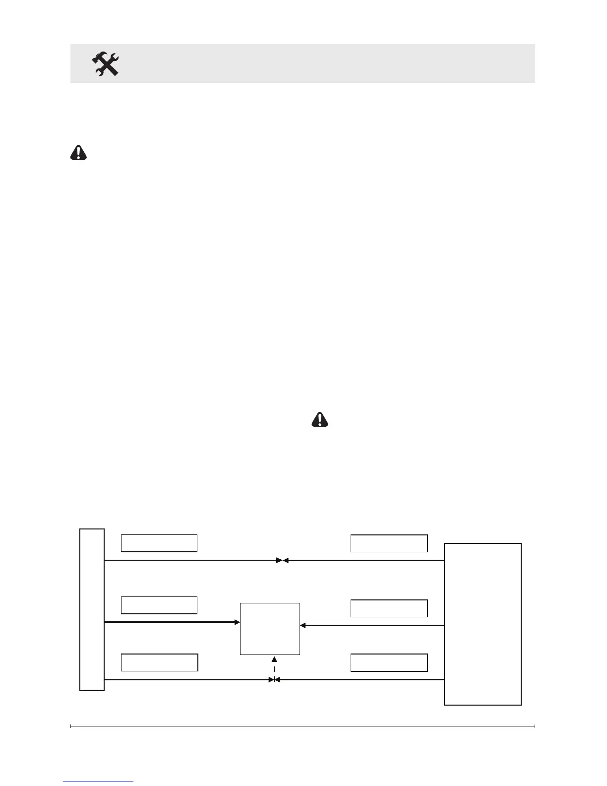
• Connect the L wire from the
unit to the live wire from the
main power through the wall
switch, ensuring all live con-
nections are connected with a
wire nut.
• Connect the N wire from the
unit to the neutral wire from
the power supply with a wire
nut.
• Connect the G wire from the
unit to the ground wire from
the power supply with a wire
nut or attach the ground-
ing wire to the cover with the
provided grounding screw, by
placing the wire in-between
screw and lock washer and
tighten (Figure 2).
• Ensure that all wires are se-
cure and do not protrude past
the ame panel, so as not to
be visible after nal assembly.
• Continue to the nal assembly
instructions.
240V Installations
Use three conductor, non-metallic
sheath cable with ground wire
(4 wires total) for the incoming
power supply on replace inserts.
CAUTION: Use the appropri-
ate wire to meet local and
national electrical codes for
rated power consumption.
• Connect the L1 wire from the