10 www.dimplex.com
Fireplace Installation
• Connect the N wire from the
unit to the neutral wire from the
power supply with a wire nut.
• Connect the G wire from the
unit to the ground wire from
the power supply with a wire
nut or attach the grounding
wire to the cover with the
provided grounding screw, by
placing the wire in-between
screw and lock washer and
tighten (Figure 3).
• Ensure that all wires are
secure and do not protrude
past the ame panel, so as
not to be visible after nal
assembly.
• Continue to the nal assembly
instructions.
120V Installation - Wall Switch
!
NOTE: Use a single pole,
single throw (On/Off) wall switch
that is rated for a minimum of
15 amps.
!
NOTE: The unit is designed to
be hardwired to a power source
and should not have a cord
installed to allow the unit to be
plugged into a wall receptacle.
Use two conductor, non-metallic
sheath cable with ground wire
(3 wires total) for the incoming
power supply.
CAUTION: Use the
appropriate wire to meet local
and national electrical codes
for rated power consumption.
• Cut the wire to an appropriate
length.
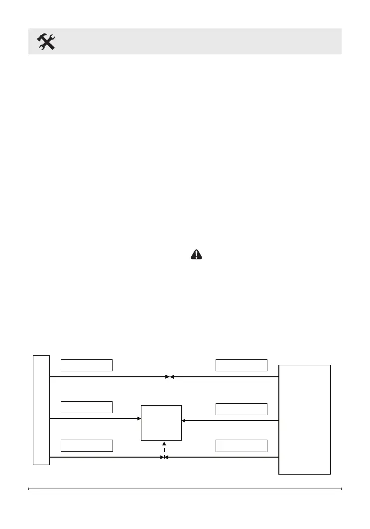
120 V
POWER
SUPPLY
(BREAKER
PANEL)
WALL
SWITCH
Figure 5