8 www.dimplex.com
Fireplace Installation
CAUTION: Sub-surface
mounting should be limited
to ½ in. (10 mm) to ensure
adequate air ow of heated air
out of the rebox area.
1. Prepare a wall with a framed
opening of 16 in. (40.6 cm)
high,
• XLF50 - 50 ⅝ in. (128.7 cm)
• XLF74 - 74 ⅝ in. (189.7 cm)
• XLF100 - 100 ⅝ in. (255.7 cm)
wide, with a bottom sill that is
a minimum of 3.5 in. (9.0 cm)
deep (Figure 2). The sill can
be constructed to support the
front of the unit to allow the
power supply wires to easily
be run behind or ush with the
back of the unit and a pass
thru hole drilled for electrical
wire routing.
WARNING: The top of the
replace is to be installed a
minimum of 8" (20.4 cm) from the
ceiling.
!
NOTE: It is recommended that
the bottom of the unit be mounted
between 30 in. (76.2 cm) and
40 in. (101.6 cm) from the ground
to maintain an optimized viewing
angle of the ame.
WARNING: Do not attempt
to wire your own new circuits. To
reduce the risk of re, electric shock
or injury to persons, always use a
licensed electrician.
WARNING: Ensure that the
circuit on which the replace is
to be installed has the power
cut off at the service panel until
installation is complete.
2. The unit is provided with an
installed ¾ in. (2.0 cm) trim.
Depending on the installation,
this trim can be removed by
removing the securing screws
and the 4 trim pieces.
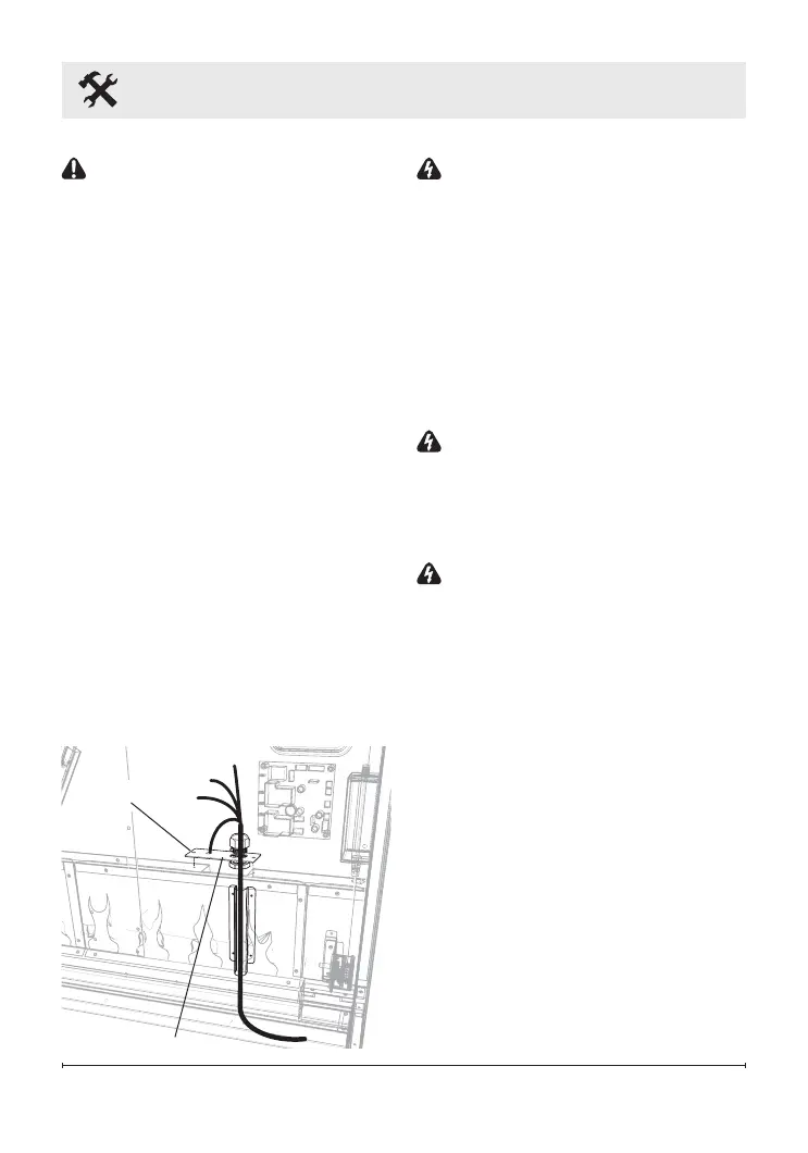
3. Ensuring a minimum of 18 in.
(46.7 cm) of slack, route the
supply power wire through a
cable clamp (not included) and
in the opening in the back of
the unit. (Figure 3)
Figure 3
Grounding
Screw
Cable Clamp