88
© 2005 Directed Electronics—all rights reserved
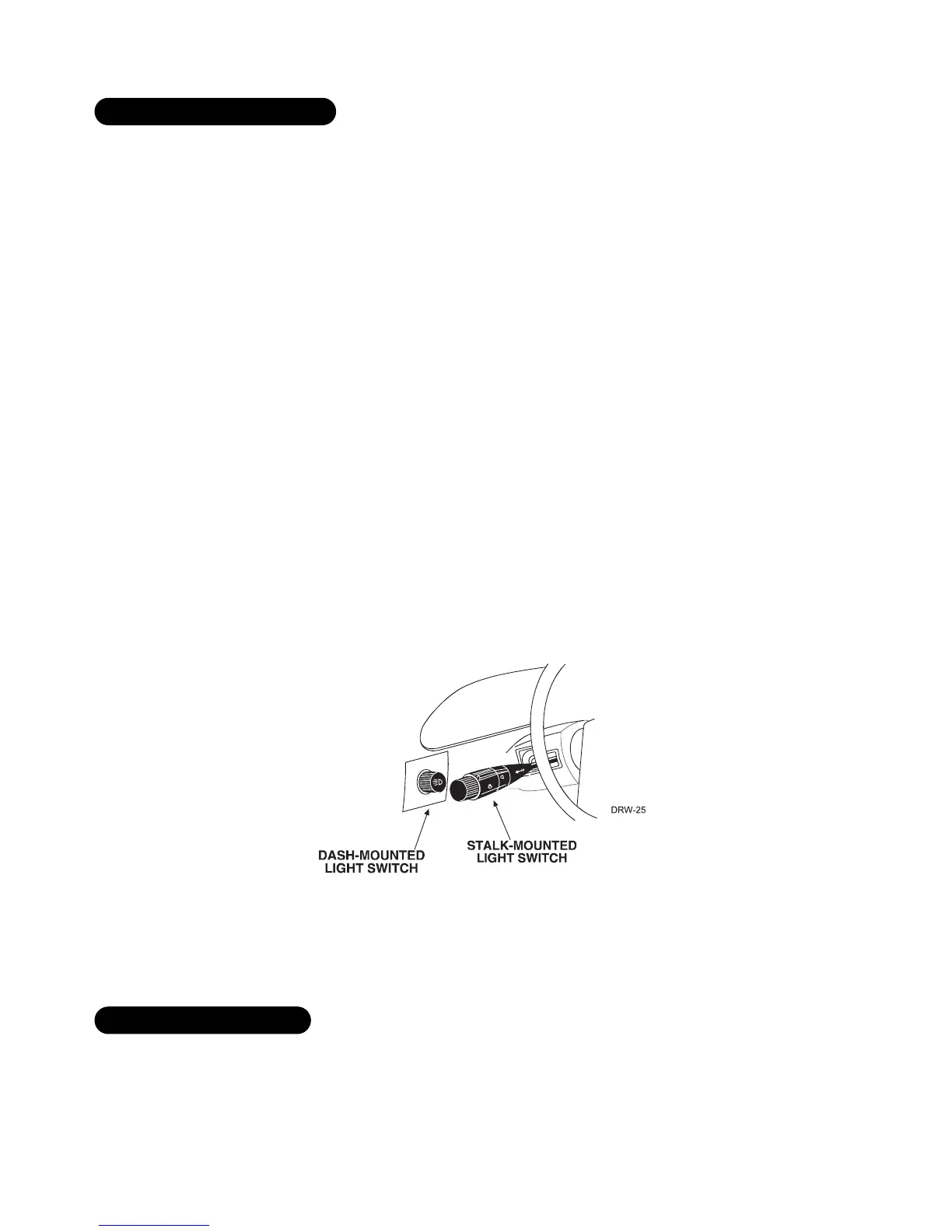
Most vehicles use a (+) parking light circuit. The (+) parking light wire is often found near the light switch. In
many vehicles the light switch is built into the turn signal lever; in these vehicles the parking light wire can be
found in the steering column. The same wire can often be accessed in the kick panel or running board.
NNOOTTEE::
Many Toyotas and other Asian vehicles, send a (-) signal from the switch to a relay. The
relay then sends (+)12V to the bulbs. Whenever you have difficulty finding a (+) parking light
wire near the switch, simply test the wires at any switch or control panel that is lit by the instru-
ment panel lighting. Remember, you need a (+) parking light wire that does not vary with the
dimmer setting.
HHooww ttoo ffiinndd aa ((++)) ppaarrkkiinngg lliigghhtt ffllaasshh wwiirree wwiitthh yyoouurr mmuullttiimmeetteerr::
1. Set to DCV or DC voltage (12V or 20V is fine).
2. Attach the (-) probe of the meter to chassis ground.
3. Probe the wire you suspect of being the parking light wire. Usually, the area near the headlight/parking light
switch is an excellent area to start, as is the kick panel.
4. Turn on the parking lights. If your meter shows (+)12V, turn off the parking lights and make sure it goes back
to zero.
5. If it does return to zero, turn the parking lights back on and, using the dash light dimmer control, turn the
brightness of the dash lights up and down. If the meter changes more than a volt when using the dimmer,
look for another wire. If it stays relatively close to (+)12V, you have found your parking light wire.
NNOOTTEE::
Vehicles that use a (-) signal from the switch to the factory relay may be interfaced
directly. (See H1/5 WHITE wire of Primary Harness (H1) Wire Connection Guide section.)
To test for a tachometer wire, a multimeter capable of testing AC voltage must be used. The tachometer wire will
show between 1V and 6V AC. In multi-coil ignition systems, the system can learn individual coil wires. Individual
coil wires in a multi-coil ignition system will register lower amounts of AC voltage. Also, if necessary, the system
ffiinnddiinngg tthhee ttaacchhoommeetteerr wwiirree
ffiinnddiinngg aa ((++)) ppaarrkkiinngg lliigghhtt wwiirree