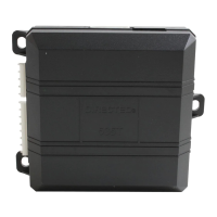
Do you have a question about the Directed 535T and is the answer not in the manual?
| Brand | Directed |
|---|---|
| Model | 535T |
| Category | Automobile Accessories |
| Language | English |
Details on how to operate the 535T system for rolling windows up, down, and venting.
Explanation of the functions programmed by the dipswitches on the module.
Verify all windows work correctly and locate driver window motor wires or master switch.
Diagram illustrating connections for a 2-window setup.
Detailed guide for connecting Main Harness 1 wires.
Detailed guide for connecting Main Harness 2 wires.
Detailed guide for connecting Main Harness 3 wires.
Wiring details for connecting to the driver side window switch.
Wiring details for connecting to the passenger side window switch.
Describes systems with central or door control modules and 535T interfacing.
Wiring diagram for systems with factory control modules on the driver side.
Wiring diagram for systems with factory control modules on the passenger side.
Diagram illustrating connections for a 4-window setup.
Description of Type A window switch output behavior, common in Domestic/Asian vehicles.
Wiring diagram for Type A window switch systems.
Description of Type B window switch wiring, involving switched ground and 12V.
Wiring diagram illustrating the relay integration for Type B systems.
Description of Type C window switch operation requiring relays for ground supply.
Wiring diagram for Type C systems focusing on front windows.
Wiring diagram for Type C systems focusing on rear windows.
Procedure to program the 535T for 2 window operation thresholds.
Conditions under which the learn routine is canceled and window travel stops.
Procedure to set the window vent position.
Conditions that cause the vent learn routine to exit.
Procedure to program the 535T for 4 window operation thresholds.
Conditions for exiting the 4-window learn routine.
 Loading...