page 21 of 44M.1k2 Hardware Guide - Version 1.3
CHAPTER 4: Operation
Clocking
M.1K2 may use a variety of clock sources:
• internal (44.1 kHz / 48kHz)
• word clock
• video (PAL / NTSC)
• a specifi c MADI input port
The system may be operated with one clock source only or may use different clock
sources at a time (PolySync™). That means that one can use a bunch of ports with
clock source ‘A’ while another portion is clocked by clock source ‘B’.
The selected clock source is output at both word clock outputs.
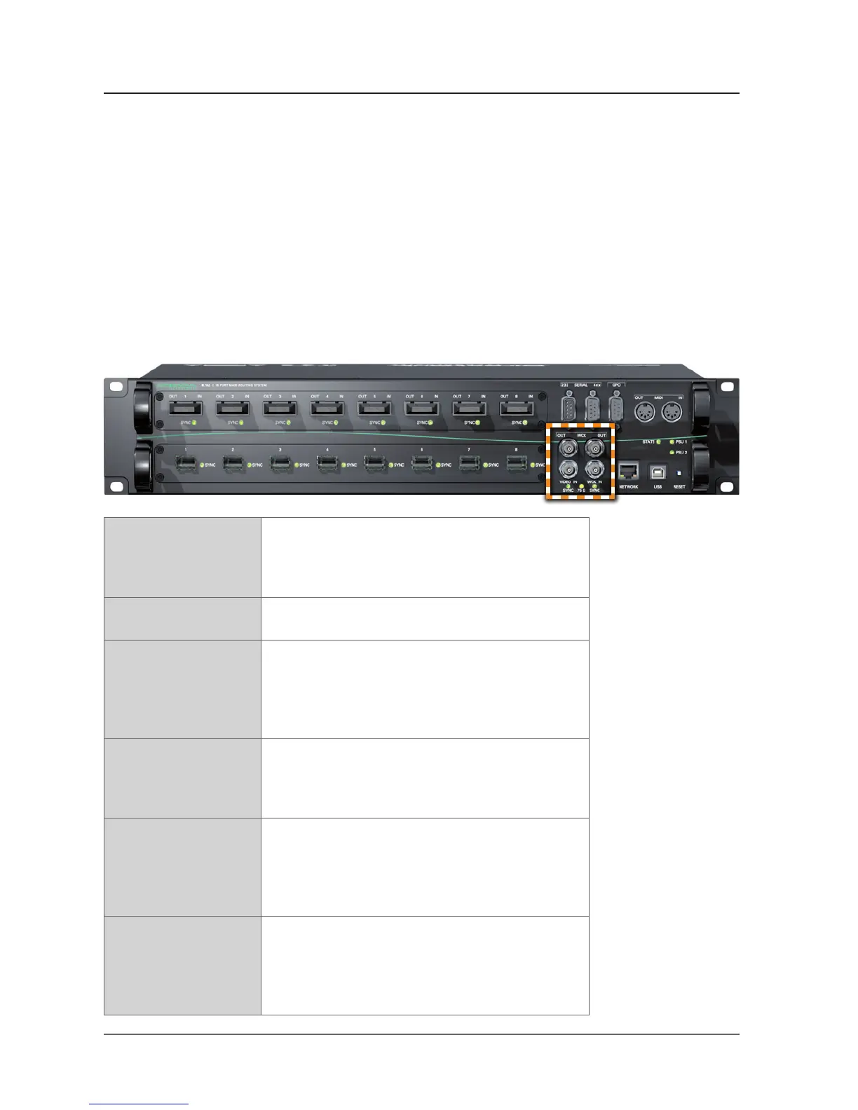
VIDEO IN 1 x BNC socket (coaxial)
Connect video reference signal here (black burst
PAL or NTSC; the video standard is detected
automatically).
WCK IN 1 x BNC socket (coaxial)
Connect word clock signal here.
WCK OUT 2 x BNC socket (coaxial)
Connect here to receive word clock output signal.
The left socket provides the base rate only (44.1 / 48
kHz). The right socket outputs full sample rate word
clock - also multiples of the base rate (2 FS / 4 FS).
75 Ω LED (yellow): indicates the termination
status of word clock and video input.
LED ON = termination enabled
LED OFF = termination disabled
SYNC (VIDEO IN) LED (green): indicates the sync status of the
incoming video signal
LED ON = signal locked
LED OFF = no signal present
LED fl ashing = signal present, not locked
SYNC (WCK IN) LED (green): indicates the sync status of the
incoming word clock signal
LED ON = signal locked
LED OFF = no signal present
LED fl ashing = signal present, not locked